
Automatic Car Parking System Using Arduino And I2C LCD Display

Introduction
In the ever changing world of technology, automation has come to be an element of our daily life. An important common use of automation is in parking systems. Car parking systems are not only handy, but they also play an important role in managing limited parking places. In this blog article, we will look at a project that focuses on developing a “Car Parking System” with Arduino. An innovative way to improve and expedite parking facilities’ efficiency is the Automatic Car Parking System with Arduino and I2C LCD Display. This creative solution automates the parking procedure by using the capabilities of Arduino, an adaptable open-source electronics platform. The system may provide real-time information on an I2C LCD Display, identify the presence of cars, and direct them to available parking places by combining sensors and actuators. This enhances the organization and usability of the parking experience in addition to optimizing the use of available parking spaces. This project is an excellent example of how ease and technology can coexist in contemporary vehicle infrastructure because of its clever automation and intuitive interface.
Components Required
- Arduino UNO
- 20×4 LCD Display
- I2C Module for the LCD
- Two IR Sensors (for entrance and exit)
- Mini Servo Motor SG-90 (for barrier control)
- Six IR Sensors (for individual parking slots)
- Power source (220V)
- Power Adapter (5V, 2A)
Proteus Simulation
Proteus is a sophisticated electronics simulation program that allows you to simulate design and test circuits before putting them into practice. This simulation serves as the foundation for the whole parking system, allowing you to see how the various components will interact.
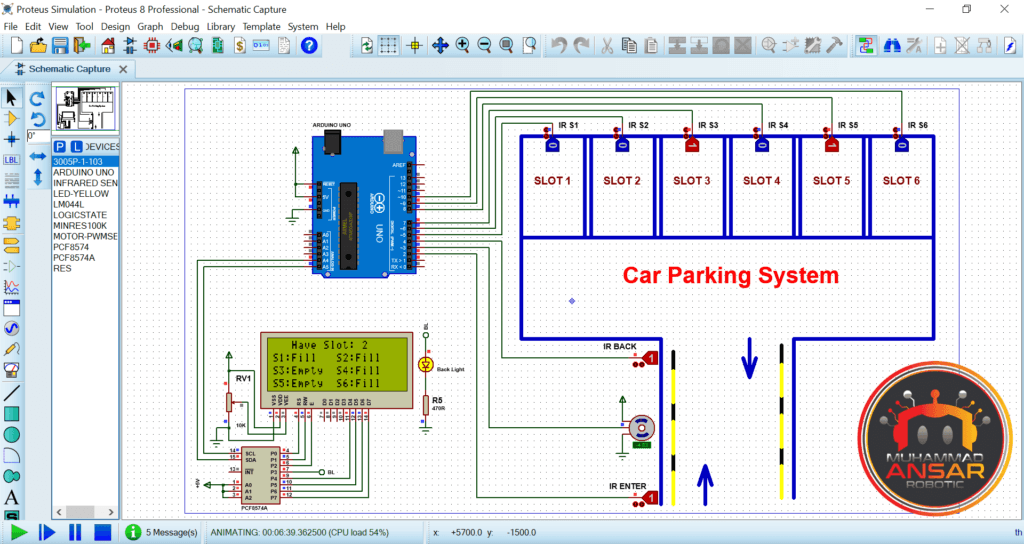
A sophisticated automobile parking system is shown in the Proteus simulation, replete with different electronic components and an Arduino microcontroller. The simulation starts with a demonstration of the essential hardware used, which include an Arduino Uno, a 20×4 LCD with an I2C module, two IR sensors, and a servo motor for barrier control. When a vehicle approaches the entry, the barrier opens, and when it passes the back sensor, it shuts. There are six spots in the parking lot, and each one has an IR (infrared) sensor to identify when a car is approaching.
The LCD shows the status of each slot; “fill” denotes a taken slot and “empty” denotes a vacant one. The connection between the sensors, barrier, and LCD is also demonstrated in the Proteus simulation, as is the dynamic updating of slot availability as automobiles arrive and depart. It is a useful tool for testing and evaluating electronic components and code logic prior to real-world deployment, assuring the auto parking system’s operation and durability.
Circuit Diagram

- Power Supply: The circuit starts with a 220-volt power source, which is then converted to 5 volts and 2 amperes using a power adapter. This 5-volt supply is used to power various components in the system.
- Arduino UNO: An Arduino UNO board is the central controller of the system. It’s responsible for processing data from sensors, controlling the servo motor, and displaying information on the LCD.
- I2C Module: An I2C module is used to interface with the 20×4 LCD (Liquid Crystal Display). It simplifies the connection between the LCD and the Arduino.
- 20×4 LCD: The 20×4 LCD is used to display information about the parking slots. It can display messages such as the availability of parking slots and other system status.
- IR Sensors: The system makes use of two infrared (IR) sensors. One sensor is at the front door, while the other one is in the back. These IR sensors detect the existence of a vehicle as it moves into or out of the parking area.
- Mini Servo Motor: It is used to regulate the opening and closing of a barrier or gate that permits or prohibits entry to a parking lot. Based on the data gathered from the IR sensors, the motor is turned on.
- Six Parking Slots: The system features six parking slots, each equipped with an individual IR sensor to detect the presence of a car in that slot. These sensors are crucial for monitoring which slots are occupied and which are vacant.
Arduino IDE Code
#include <Servo.h> //includes the servo library
#include <Wire.h>
#include <LiquidCrystal_I2C.h>
LiquidCrystal_I2C lcd(0x27, 2, 1, 0, 4, 5, 6, 7, 3, POSITIVE);
Servo myservo;
#define ir_enter 2
#define ir_back  4
#define ir_car1 5
#define ir_car2 6
#define ir_car3 7
#define ir_car4 8
#define ir_car5 9
#define ir_car6 10
int S1=0, S2=0, S3=0, S4=0, S5=0, S6=0;
int flag1=0, flag2=0;
int slot = 6;
void setup(){
Serial.begin(9600);
pinMode(ir_car1, INPUT);
pinMode(ir_car2, INPUT);
pinMode(ir_car3, INPUT);
pinMode(ir_car4, INPUT);
pinMode(ir_car5, INPUT);
pinMode(ir_car6, INPUT);
pinMode(ir_enter, INPUT);
pinMode(ir_back, INPUT);

myservo.attach(3);
myservo.write(90);
lcd.begin(20, 4);
lcd.setCursor (0,1);
lcd.print("    Car  parking  ");
lcd.setCursor (0,2);
lcd.print("       System     ");
delay (2000);
lcd.clear();
Read_Sensor();
int total = S1+S2+S3+S4+S5+S6;
slot = slot-total;
}
void loop(){
Read_Sensor();
lcd.setCursor (0,0);
lcd.print("   Have Slot: ");
lcd.print(slot);
lcd.print("    ");
lcd.setCursor (0,1);
if(S1==1){lcd.print("S1:Fill ");}
     else{lcd.print("S1:Empty");}
lcd.setCursor (10,1);
if(S2==1){lcd.print("S2:Fill ");}
     else{lcd.print("S2:Empty");}
lcd.setCursor (0,2);
if(S3==1){lcd.print("S3:Fill ");}
     else{lcd.print("S3:Empty");}
lcd.setCursor (10,2);
if(S4==1){lcd.print("S4:Fill ");}
     else{lcd.print("S4:Empty");}
 lcd.setCursor (0,3);
if(S5==1){lcd.print("S5:Fill ");}
     else{lcd.print("S5:Empty");}
lcd.setCursor (10,3);
if(S6==1){lcd.print("S6:Fill ");}
     else{lcd.print("S6:Empty");}
if(digitalRead (ir_enter) == 0 && flag1==0){
if(slot>0){flag1=1;
if(flag2==0){myservo.write(180); slot = slot-1;}
}else{
lcd.setCursor (0,0);
lcd.print(" Sorry Parking Full ");
delay(1500);
}
}
if(digitalRead (ir_back) == 0 && flag2==0){flag2=1;
if(flag1==0){myservo.write(180); slot = slot+1;}
}
if(flag1==1 && flag2==1){
delay (1000);
myservo.write(90);
flag1=0, flag2=0;
}
delay(1);
}
void Read_Sensor(){
S1=0, S2=0, S3=0, S4=0, S5=0, S6=0;
if(digitalRead(ir_car1) == 0){S1=1;}
if(digitalRead(ir_car2) == 0){S2=1;}
if(digitalRead(ir_car3) == 0){S3=1;}
if(digitalRead(ir_car4) == 0){S4=1;}
if(digitalRead(ir_car5) == 0){S5=1;}
if(digitalRead(ir_car6) == 0){S6=1;}
}
Explanation:
- Include Libraries:
Servo.h: This library is used for controlling the servo motor.Wire.h: Used for I2C communication with the LCD.LiquidCrystal_I2C.h: This library simplifies controlling the 20×4 LCD screen using I2C communication.
- Servo Motor and IR Sensor Definitions:
- The code defines pins for the servo motor and IR sensors. For example,
ir_enteris defined as pin 2 for the entrance sensor, andir_backis defined as pin 4 for the back sensor.
- The code defines pins for the servo motor and IR sensors. For example,
- IR Sensor Variables:
- The state of each parking place is stored in the variables S1, S2, S3, S4, S5, and S6 (1 or 0).
- When an automobile is arriving or leaving, the variables flag1 and flag2 are utilized as flags to monitor this information.
slotvariable keeps track of the number of available parking slots.
- Setup Function:
- The
setup()function initializes the serial communication, pin modes for IR sensors, and the servo motor. - It initializes the LCD and displays a welcome message for 2 seconds.
Read_Sensor()function is called to read the initial status of parking slots and calculate the number of available slots.
- The
- Loop Function:
- The
loop()function continuously runs the main logic of the system. - It calls
Read_Sensor()to update the status of parking slots. - It displays the number of available slots and the status of each slot on the LCD.
- It checks the status of entrance and back IR sensors to determine if a car is entering or exiting.
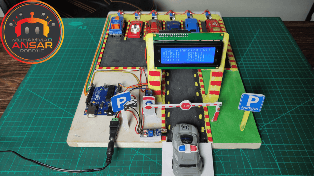
- When a car enters, it checks if there are available slots and opens the barrier (servo motor) while decrementing the available slot count. If parking is full, it displays a “Parking Full” message.
- When a car exits, it opens the barrier and increments the available slot count.
- After a delay, the barrier is closed, and the flags are reset.
- The
- Read_Sensor Funct
- The
Read_Sensor()function is used to read the status of the IR sensors for all parking slots and update the corresponding variablesS1toS6. The sensor values are stored in variables S1 through S6, each of which is associated with a particular parking spot. The code checks the condition of each infrared sensor (ir_car1 through ir_car6) using the digitalRead function. The associated S variable is set to 1, indicating that the relevant parking spot is occupied, if the sensor detects the presence of an automobile (returns a logic low or 0). It is noteworthy that the code given initializes all S variables to 0 before to reading the sensors, so guaranteeing a fresh start for every sensor reading loop.
- The
Hardware Testing
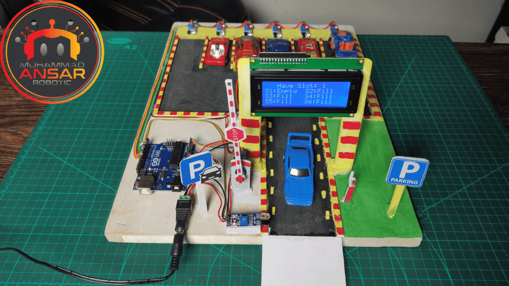
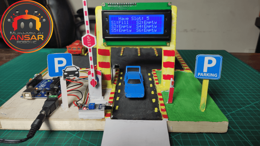
It’s time for hardware testing when you’ve finished the simulation, uploaded the code to your Arduino, and constructed the circuit according to the circuit design. This phase includes real-world testing to confirm that the auto parking system works properly. You’ll witness how the system reacts when a car enters, parks, and departs. The LCD panel will show information about available parking places in real time.
Conclusion
Finally, this project exhibits the power of automation or microcontroller-based control systems. You may construct an effective and user-friendly parking solution by integrating Arduino, several sensors, and a servo motor. The benefits of such a system are improved management of parking, fewer human interactions, and more client convenience. This project exemplifies how technology advancements may improve the efficacy and management of urban surroundings. This project provides an excellent chance to gain knowledge about and experiment with various electronic components and code, whether you are an enthusiast for technology or a hobbyist. Now that you’ve completed this intriguing Car Parking System project, you’re ready to dive into the realm of automatic parking.
13 responses to “Automatic Car Parking System Using Arduino And I2C LCD Display”

How to Connect IOT Application ??
contact my whatsapps number
Please explain Read_sensor(); function in detail.
contacts in my whatsapp number
I’m getting error ‘POSITIVE’ was not declared in this scope
Liquid crystal no such file or directory
i have completed all the connections and compiled the code but my adaptor is blinking and project isn’t starting.
maybe there is a problem with the address of your I2C lcd module
How i want to contact you? Because it can’t display the parking
LiquidCrystal_I2C lcd(0x27, 2, 1, 0, 4, 5, 6, 7, 3, POSITIVE);
^~~~~~~~exit status 1
Compilation error: ‘POSITIVE’ was not declared in this scope
Great article! I appreciate the clear and insightful perspective you’ve shared. It’s fascinating to see how this topic is developing. For those interested in diving deeper, I found an excellent resource that expands on these ideas: check it out here. Looking forward to hearing others’ thoughts and continuing the discussion!
This article had me hooked! For those curious, here’s more: DISCOVER MORE. What are your thoughts?
It is very valuable phrase


13 thoughts on “Automatic Car Parking System Using Arduino And I2C LCD Display”
 hakar says:
How to Connect IOT Application ??
- Darshan Dugar says:
Please explain Read_sensor(); function in detail.
- Suhani says:
I’m getting error ‘POSITIVE’ was not declared in this scope
- Suma. says:
Liquid crystal no such file or directory
- soham says:
i have completed all the connections and compiled the code but my adaptor is blinking and project isn’t starting.
- Memy says:
How i want to contact you? Because it can’t display the parking
- Gyle says:
LiquidCrystal_I2C lcd(0x27, 2, 1, 0, 4, 5, 6, 7, 3, POSITIVE);
^~~~~~~~exit status 1
Compilation error: ‘POSITIVE’ was not declared in this scope
Great article! I appreciate the clear and insightful perspective you’ve shared. It’s fascinating to see how this topic is developing. For those interested in diving deeper, I found an excellent resource that expands on these ideas: check it out here. Looking forward to hearing others’ thoughts and continuing the discussion!
This article had me hooked! For those curious, here’s more: DISCOVER MORE. What are your thoughts?
Leave a Reply