
Arduino Based pH Sensor Interfacing And Calibration

Introduction
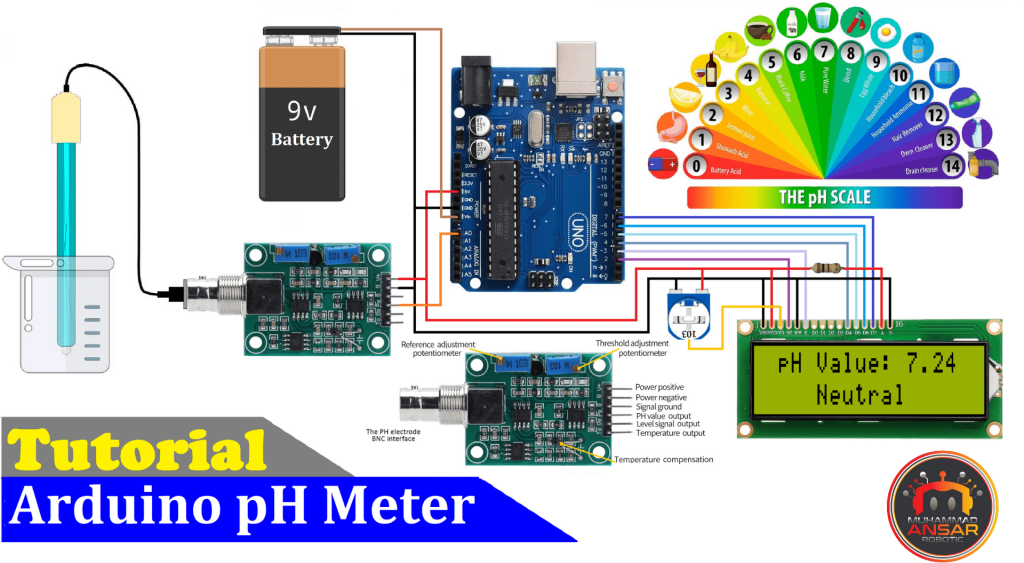
In several disciplines, including chemistry, aquaculture, agriculture, and environmental monitoring, pH measurement is an essential parameter. In this project, we’ll investigate the development of an accurate pH meter using an Arduino platform. Integrating pH meters with an Arduino can provide real-time monitoring as well as information logging. pH meters are crucial instruments for assessing the acidity or alkalinity of a solution. We will walk you through the necessary parts, the circuit schematic, the Proteus simulation, and hardware testing so you can assemble your own Arduino pH tester. Explore the most recent MArobotics Blogs lesson on Arduino-based pH sensor interface and calibration. Explore the step-by-step method to smoothly integrating a pH sensor with Arduino, as well as the necessary calibration processes for precise and dependable pH measurements in your projects.
Components Required
- Arduino UNO
- 16×2 LCD Display
- pH Sensor Module
- 10k Variable Resistor
- 100Ω Resistor
- Male to Male Jumper Wires
- Male to Female Jumper Wires
- Hard Jumper Wire
- Battery Clip
- 9V Battery
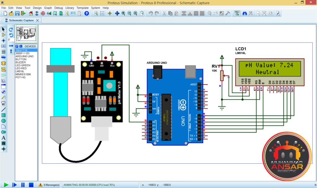
Proteus Simulation
Making a hex file for the Arduino code that will execute the simulation is the first step. For you to do so, open the Arduino code in the Arduino IDE. Then select the “Arduino Uno” board from the “Tools” menu. After that, the code undergoes compilation to produce a hex file.
The hex file’s address is transferred as soon as it has been correctly compiled.
The code is loaded into the simulated Arduino by the author clicking on the Arduino component in the Proteus simulation, pasting the copied address of the hex file, and selecting “OK”.
The simulation is executed after the code has been loaded. The LCD simulates a startup phase by displaying a message for a 2000-millisecond delay during the simulation.
The pH value will appear on the first line of the LCD, followed by the status (showing either the fluid is neutral, acidic, or alkaline). The LCD status changes based on the pH value:
- If the pH value is between 7 and 8, it displays “Neutral.”
- If the pH value exceeds 8, it indicates “Alkaline.”
- If the pH value drops below 7, it indicates “Acidic.”
The LCD displays “Alkaline” and “Very Alkaline” as the pH reading rises over certain thresholds. On the other hand, as the pH value falls below particular pH values, it signifies “Acidic” and “Very Acidic.”
This simulation offers a useful and instructional tool for comprehending the project’s functioning prior to physically implementing it by assisting users in visualizing how the Arduino-based pH sensor system functions and interprets pH measurements.
Circuit Diagram
In the circuit diagram, we have used a 9 volts battery for power source. An Arduino UNO is used as a microcontroller. A pH sensor is attached to A0 pin of the Arduino UNO. A LCD of 16×2 is used for displaying the pH value. At the contrast setting pin of the LCD, a 10k potentiometer is used. Pins 15 and 16 are the backlight pins of the LCD. Pin 16 is directly attached to the ground. And from pin 15, a 100-ohm resistance is used in series with the positive. Make accurate connections for proper working.
Arduino IDE Code
#include <LiquidCrystal.h>
LiquidCrystal lcd(2, 3, 4, 5, 6, 7);
#define SensorPin A0      //pH meter Analog output to Arduino Analog Input 0
float calibration_value = 21.34 + 0.7;
unsigned long int avgValue;  //Store the average value of the sensor feedback
int buf[10], temp;
void setup(){
pinMode(SensorPin, INPUT);

lcd.begin(16, 2);
lcd.clear();
lcd.setCursor(0, 0);
lcd.print("Welcome To");
lcd.setCursor(0, 1);
lcd.print("       pH Meter");
delay(2000);
lcd.clear();
}
void loop(){

 for(int i=0;i<10;i++){ //Get 10 sample value from the sensor for smooth the value
    buf[i]=analogRead(SensorPin);
    delay(10);
  }
  for(int i=0;i<9;i++){ //sort the analog from small to large
    for(int j=i+1;j<10;j++){
      if(buf[i]>buf[j]){
        temp=buf[i];
        buf[i]=buf[j];
        buf[j]=temp;
      }
    }
  }
  avgValue=0;
  for(int i=2;i<8;i++)avgValue+=buf[i];  //take the average value of 6 center sample

  float phValue=(float)avgValue*5.0/1024/6; //convert the analog into millivolt
  phValue = -5.70 * phValue + calibration_value; //convert the millivolt into pH value

  lcd.setCursor(0, 0);
  lcd.print(" pH Value: ");
  lcd.print(phValue);
  lcd.print("  ");

  lcd.setCursor(1, 1);
     if(phValue<4)                 lcd.print(" Very Acidic ");
else if(phValue>=4  && phValue<5)  lcd.print("    Acidic   ");
else if(phValue>=5  && phValue<7)  lcd.print(" Acidic-ish  ");
else if(phValue>=7  && phValue<8)  lcd.print("   Neutral   ");
else if(phValue>=8  && phValue<10) lcd.print("Alkaline-ish ");
else if(phValue>=10 && phValue<11) lcd.print("  Alkaline   ");
else if(phValue>=11)               lcd.print("Very alkaline");

  delay(1000);
}
Explanation:
Importing the LiquidCrystal library is the first step because it is essential for managing the 16×2 LCD screen. The code initializes the analog pin A0 for the pH sensor and a number of pins used to connect the LCD. Furthermore, a calibration variable is included, which enables the pH sensor’s results to be adjusted. To make processing data easier, a number of variables have been defined. The LCD display is cleared and initialized, and the pH sensor pin is set up as an input in the setup function. A welcome message is displayed on the LCD to improve user comprehension in the first stage. The loop function, which reads analog pH levels and samples data with a 10-millisecond delay to maintain stability, is the central component of the project.
Ten samples are used to obtain the average pH value, which lowers measurement noise. Next, using a formula that takes into consideration both the maximum voltage and the maximum value of the ADC, this analog value is translated into a pH value. The calibration variable is used to change this pH value. After that, the code refreshes the LCD, showing the liquid’s state (alkaline, acidic, or neutral) on the second line and the pH number on the first. To maintain a constant flow of pH data updates, the loop is regulated by a 1-second delay. Lastly, the code mentions that the pH sensor has a calibration potentiometer, which enables calibration changes to improve pH reading accuracy.
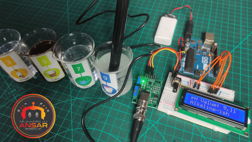
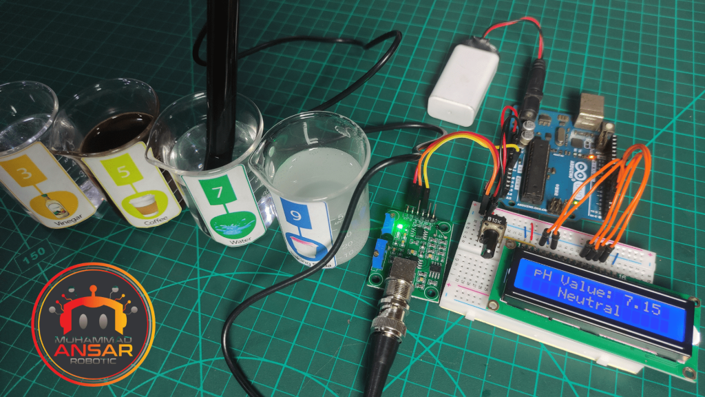
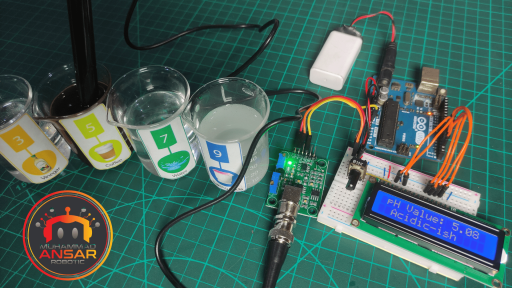
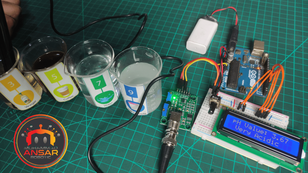
Hardware Testing
Upload the code on Arduino. Turn the power on. By placing the pH sensor in different liquids, their pH value is displayed on the LCD and their type is also shown.
Conclusion
In order to develop a flexible pH meter, this project shows how to connect and calibrate an Arduino with a pH sensor. You may build your own pH meter using the directions provided in this blog post for use in analyzing the quality of water and hydroponic systems, among other things. Because it allows for real-time pH tracking and data logging, this project is helpful for industry and research. pH meters are an example of the many potential uses that arise when sensors and electronics are combined with Arduino’s versatility. We hope that this project has been educational and encourages you to research more advancements in the field of sensor interface and DIY electronics.


Leave a Reply