
Line Follower Obstacle Avoiding Robot Using Arduino And L298 Motor Driver

Introduction
In this fascinating project, we’ll investigate the use of an Arduino and an L298 Motor Driver to create a Line Follower Robot that can avoid obstacles. Robots that follow lines are extensively employed in several sectors for activities like moving objects and engaging in entertaining events like robotic racing. This project creates a flexible and dynamic robot by fusing the intelligence to avoid obstacles with the precision of line following. With the Arduino IDE and a variety of components, you can build an intelligent robot that can navigate through challenging settings.
Components Required
- Solderless Breadboard
- 4-wheel Robot Car Kit
- Arduino UNO
- IR Sensor x 2
- L298 Motor Driver
- Mini Servo Motor SG90
- Ultrasonic Sensor Holder
- Ultrasonic Sensor HC-SR04
- 4Pcs Smart Robot Car Tyers Wheels
- Male to Female Jumper Wires
- Male to Male Jumper Wires
- Hard Jumper Wire
- On/Off Switch
- 18650 Battery Holder – 2 Cell
- 18650 Battery Cell 3.7V x 2
Circuit Diagram
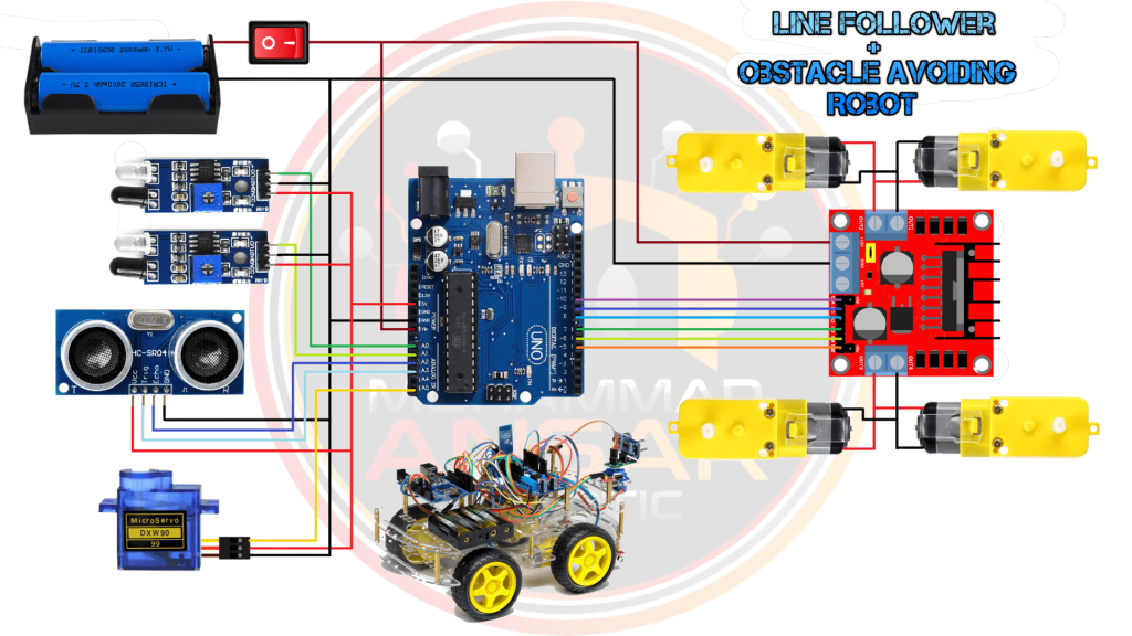
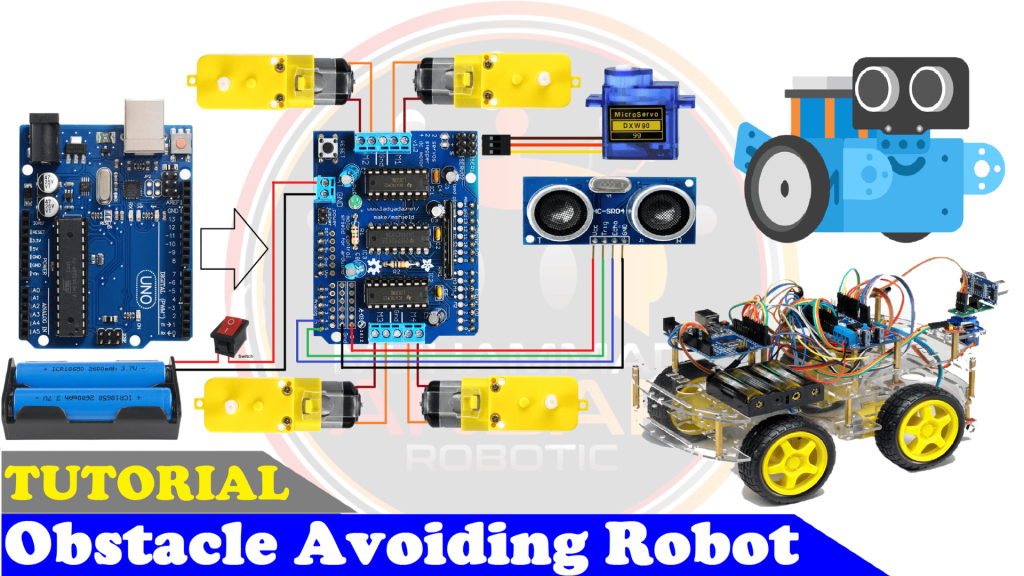
According to the circuit schematic for the project “Line Follower with Obstacle Avoiding Robot,” a thorough setup is needed for the robot to operate. The main power source is made up of two 3.7-volt batteries connected in series to provide 7.4 volts overall. A power switch is included in for easy on/off control. An Arduino UNO, two infrared (IR) sensors for line-following on the left and right sides, an ultrasonic sensor (HC-SR04) for identifying obstacles, and a tiny servo motor are the main parts. While following a black line is the robot’s main task, it can also navigate obstacles by using an ultrasonic sensor to detect their closeness on either side. The two DC gear motors that enable both clockwise and counterclockwise rotation depend on the L298 Motor Driver. The left and right side motors are controlled by different pins on the L298 that are connected to the Arduino in a certain way, allowing for speed control. The L298 is connected to a 12V positive and ground connector to deliver power to the motors. This circuit schematic provides the framework for constructing the project’s hardware.
Arduino IDE Code
#define enA 10//Enable1 L298 Pin enA
#define in1 9 //Motor1  L298 Pin in1
#define in2 8 //Motor1  L298 Pin in1
#define in3 7 //Motor2  L298 Pin in1
#define in4 6 //Motor2  L298 Pin in1
#define enB 5 //Enable2 L298 Pin enB
#define L_S A0 //ir sensor Left
#define R_S A1 //ir sensor Right
#define echo A2    //Echo pin
#define trigger A3 //Trigger pin
#define servo A5
int Set=15;
int distance_L, distance_F, distance_R;
void setup(){ // put your setup code here, to run once
Serial.begin(9600); // start serial communication at 9600bps
pinMode(R_S, INPUT); // declare if sensor as input
pinMode(L_S, INPUT); // declare ir sensor as input
pinMode(echo, INPUT );// declare ultrasonic sensor Echo pin as input
pinMode(trigger, OUTPUT); // declare ultrasonic sensor Trigger pin as Output
pinMode(enA, OUTPUT); // declare as output for L298 Pin enA
pinMode(in1, OUTPUT); // declare as output for L298 Pin in1
pinMode(in2, OUTPUT); // declare as output for L298 Pin in2
pinMode(in3, OUTPUT); // declare as output for L298 Pin in3
pinMode(in4, OUTPUT); // declare as output for L298 Pin in4
pinMode(enB, OUTPUT); // declare as output for L298 Pin enB
analogWrite(enA, 200); // Write The Duty Cycle 0 to 255 Enable Pin A for Motor1 Speed
analogWrite(enB, 200); // Write The Duty Cycle 0 to 255 Enable Pin B for Motor2 Speed
pinMode(servo, OUTPUT);
 for (int angle = 70; angle <= 140; angle += 5)  {
   servoPulse(servo, angle);  }
 for (int angle = 140; angle >= 0; angle -= 5)  {
   servoPulse(servo, angle);  }
 for (int angle = 0; angle <= 70; angle += 5)  {
   servoPulse(servo, angle);  }
distance_F = Ultrasonic_read();
delay(500);
}
void loop(){
//==============================================
//     Line Follower and Obstacle Avoiding
//==============================================
distance_F = Ultrasonic_read();
Serial.print("D F=");Serial.println(distance_F);
//if Right Sensor and Left Sensor are at White color then it will call forword function
 if((digitalRead(R_S) == 0)&&(digitalRead(L_S) == 0)){
  if(distance_F > Set){forword();}
                  else{Check_side();}
 }

//if Right Sensor is Black and Left Sensor is White then it will call turn Right function
else if((digitalRead(R_S) == 1)&&(digitalRead(L_S) == 0)){turnRight();}
//if Right Sensor is White and Left Sensor is Black then it will call turn Left function
else if((digitalRead(R_S) == 0)&&(digitalRead(L_S) == 1)){turnLeft();}

delay(10);
}
void servoPulse (int pin, int angle){
int pwm = (angle*11) + 500;      // Convert angle to microseconds
 digitalWrite(pin, HIGH);
 delayMicroseconds(pwm);
 digitalWrite(pin, LOW);
 delay(50); // Refresh cycle of servo
}
//**********************Ultrasonic_read****************************
long Ultrasonic_read(){
  digitalWrite(trigger, LOW);
  delayMicroseconds(2);
  digitalWrite(trigger, HIGH);
  delayMicroseconds(10);
  long time = pulseIn (echo, HIGH);
  return time / 29 / 2;
}
void compareDistance(){
    if(distance_L > distance_R){
  turnLeft();
  delay(500);
  forword();
  delay(600);
  turnRight();
  delay(500);
  forword();
  delay(600);
  turnRight();
  delay(400);
  }
  else{
  turnRight();
  delay(500);
  forword();
  delay(600);
  turnLeft();
  delay(500);
  forword();
  delay(600);
  turnLeft();
  delay(400);
  }
}
void Check_side(){
    Stop();
    delay(100);
 for (int angle = 70; angle <= 140; angle += 5)  {
   servoPulse(servo, angle);  }
    delay(300);
    distance_R = Ultrasonic_read();
    Serial.print("D R=");Serial.println(distance_R);
    delay(100);
  for (int angle = 140; angle >= 0; angle -= 5)  {
   servoPulse(servo, angle);  }
    delay(500);
    distance_L = Ultrasonic_read();
    Serial.print("D L=");Serial.println(distance_L);
    delay(100);
 for (int angle = 0; angle <= 70; angle += 5)  {
   servoPulse(servo, angle);  }
    delay(300);
    compareDistance();
}
void forword(){  //forword
digitalWrite(in1, LOW); //Left Motor backword Pin
digitalWrite(in2, HIGH); //Left Motor forword Pin
digitalWrite(in3, HIGH); //Right Motor forword Pin
digitalWrite(in4, LOW); //Right Motor backword Pin
}
void backword(){ //backword
digitalWrite(in1, HIGH); //Left Motor backword Pin
digitalWrite(in2, LOW); //Left Motor forword Pin
digitalWrite(in3, LOW); //Right Motor forword Pin
digitalWrite(in4, HIGH); //Right Motor backword Pin
}
void turnRight(){ //turnRight
digitalWrite(in1, LOW); //Left Motor backword Pin
digitalWrite(in2, HIGH); //Left Motor forword Pin
digitalWrite(in3, LOW); //Right Motor forword Pin
digitalWrite(in4, HIGH); //Right Motor backword Pin
}
void turnLeft(){ //turnLeft
digitalWrite(in1, HIGH); //Left Motor backword Pin
digitalWrite(in2, LOW); //Left Motor forword Pin
digitalWrite(in3, HIGH); //Right Motor forword Pin
digitalWrite(in4, LOW); //Right Motor backword Pin
}
void Stop(){ //stop
digitalWrite(in1, LOW); //Left Motor backword Pin
digitalWrite(in2, LOW); //Left Motor forword Pin
digitalWrite(in3, LOW); //Right Motor forword Pin
digitalWrite(in4, LOW); //Right Motor backword Pin
}
Explanation
First, the code initializes a number of Arduino pins, such as the L298 Motor Driver, the left and right infrared sensors, and the ultrasonic sensor. Certain pins are designated for regulating motor speed, while the rest of the pins are configured as inputs and outputs. To make obstacle identification and avoidance easier, the code makes use of an ultrasonic sensor and servo motor. Interestingly, the code includes a logic that determines whether the robot ought to turn left or right to prevent obstacles by comparing the distances measured by the ultrasonic sensor. The code also includes routines for halting, turning left or right, and moving forward—all essential for the robot’s ability to follow lines and avoid obstacles. Following is the complete details:
- Pin Definitions:
- Motor control pins (enA, in1, in2, in3, in4, enB).
- Infrared sensors pins for line following (L_S, R_S).
- Ultrasonic sensor pins (echo, trigger).
- Servo motor pin (servo).
- Setup:
- Initialize serial communication.
- Set pins as input or output.
- Set initial motor speeds using PWM (analogWrite).
- Move the servo motor through a sequence of angles to establish its initial position.
- Read the initial distance using the ultrasonic sensor.
- Loop:
- Continuously reads the distance from the ultrasonic sensor.
- Uses infrared sensors for line following and obstacle detection.
- Executes different movements based on sensor readings:
- Forwards (
forword()) if both line-following sensors detect white and the distance is greater than a set value. - Turns right (
turnRight()) if the right sensor is on a black line and the left sensor is on a white surface. - Turns left (
turnLeft()) if the left sensor is on a black line and the right sensor is on a white surface. - If both line-following sensors detect a black line, it checks the distance and performs a series of maneuvers (
compareDistance()) to avoid obstacles. - Stops (
Stop()) after each movement to ensure the robot halts.
- Forwards (
- ServoPulse Function:
- Generates pulses to control the servo motor angle.
- Ultrasonic_read Function:
- Uses an ultrasonic sensor to measure distance.
- Check_side and compareDistance Functions:
- These functions are called to check the distance on the left and right sides and determine the appropriate action based on the comparison.
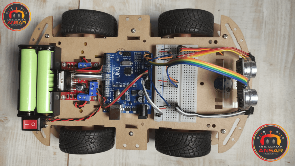
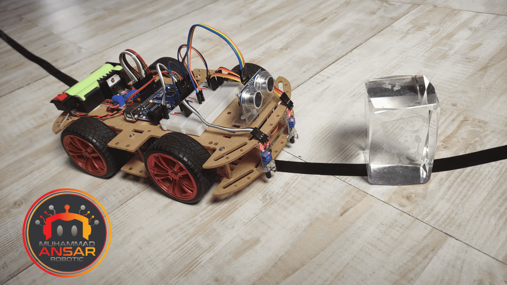
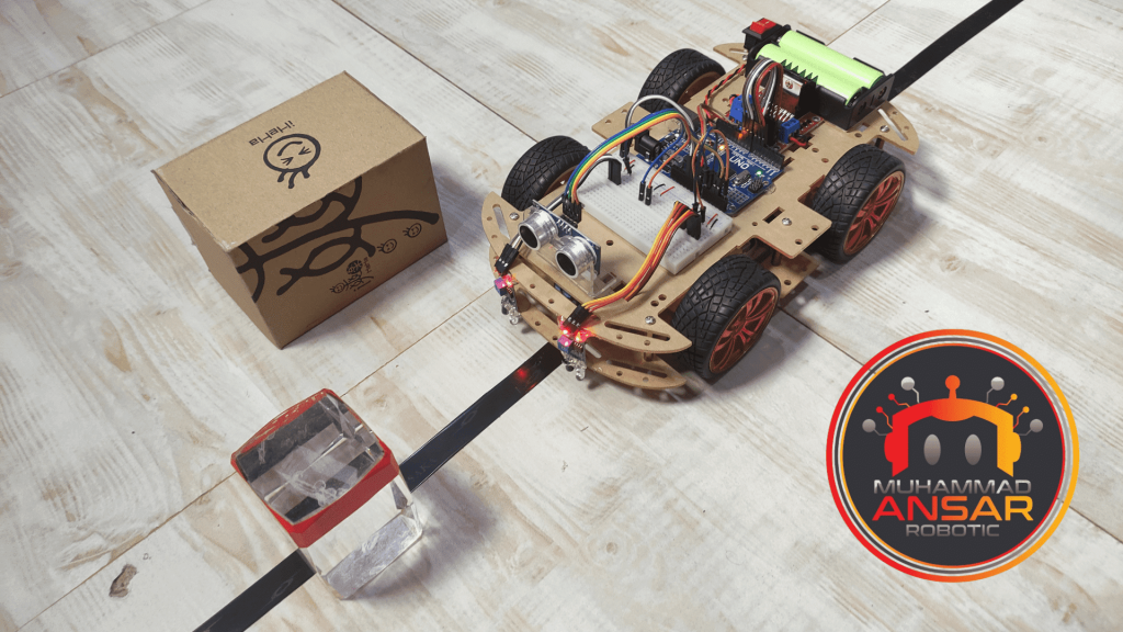
Hardware Testing
Turning on the robot is the first stage; next, the IR sensors must be calibrated to make sure they react appropriately to surface color changes, which is essential for line following and obstacle avoidance. Through this tuning procedure, the sensors’ ability to recognize obstacles and the track is guaranteed. The robot is seen responding to manual orders by pausing, turning right, moving ahead, traveling backward, and executing different combinations of these actions.
Conclusion
This project demonstrates the creation of a flexible line follower robot that can avoid obstacles. It was made possible via Arduino and the L298 Motor Driver. A variety of parts, such as infrared and ultrasonic sensors, have been combined to build a robot that can follow lines and navigate around obstacles with intelligence. In addition to offering insightful information on robotics and Arduino programming, this project is entertaining and useful for students, hobbyists, and robot lovers.
3 responses to “Line Follower Obstacle Avoiding Robot Using Arduino And L298 Motor Driver”

Reach me out sir! I want tk buy this pre ready project is there any way to buy this. Answer.e asap!!
great sir
thank you


Related Posts
Arduino Based Black Line Follower Robot
Obstacle Avoiding Robot Using Arduino UNO And L293D With HC-SR04 Sensor
3 thoughts on “Line Follower Obstacle Avoiding Robot Using Arduino And L298 Motor Driver”
 Md Aquib Izhar says:
Reach me out sir! I want tk buy this pre ready project is there any way to buy this. Answer.e asap!!
- sarjantpal says:
great sir
Leave a Reply