
Password Based Door Lock System Using Arduino And Keypad

Introduction
Security is vital in the fast-paced world we live in today. There has never been a more important time to secure our residences and private areas. That’s why an Arduino and keypad-based password-based door lock system is useful. We will go into more depth about this creative concept in this blog article, which provides an economical and practical way to improve security. We can create a reliable and adaptable door locking system that requires a strong password to open by combining an Arduino, a keypad, and an L298 motor driver. Let’s look at the parts needed and how to make this keypad door lock.
Components Required
- Drawing Board
- 3mm Acrylic Sheet
- Arduino UNO
- I2C LCD Module
- 16×2 LCD Display
- 4×3 Keypad
- Buzzer
- L298 Motor Driver
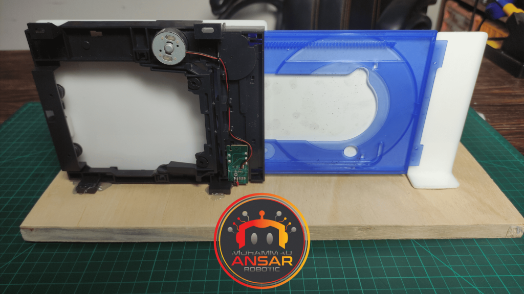
- DVD Room Gate (assuming you mean a DVD drive or optical drive)
- Male to Male Jumper Wires
- Male to Female Jumper Wires
- Female DC Power Jack
- 5V 2Amp Power Adapter
Proteus Simulation
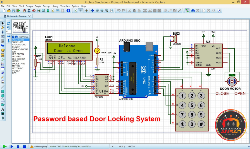
The simulation highlights the main functions of the system and offers a hands-on explanation of how it works. An Arduino UNO, an I2C LCD module (16×2 LCD display), a 4×3 keypad, an L298 Motor Driver, a DVD room gate, and a buzzer are among the many parts used in the project. They are all painstakingly placed on a drawing board covered in a 3mm acrylic sheet.
The door is closed when the simulation starts and an initial message appears on the LCD. After entering the right password on the keypad, the door opens and the motor rotates in a clockwise direction for a certain amount of time. The door stays open for a certain amount of time before the motor turns the door closed by rotating counterclockwise. The system gives users three chances to input the correct password in the case that they type it incorrectly. A 10-second delay is applied after three unsuccessful tries in a row, and an alert signaling a security breach sounds. Password changes can also be made through the system by entering the desired new password after the existing code. The access code is modified when a password change is successful.
Circuit Diagram
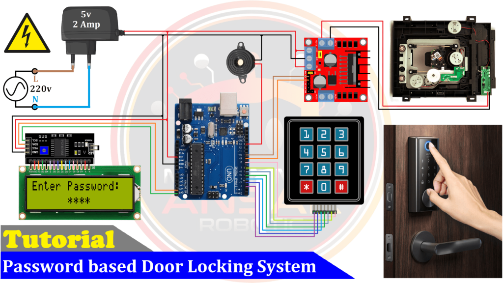
This circuit schematic provides a thorough visual depiction of the Arduino and Keypad-based password-based door lock system. The physical components and their connections are clearly the focus of the system’s design, which aims to improve security and restrict access to a certain region. An Arduino UNO functions as the central processing unit of the system. With the help of an I2C LCD module attached to the A4 and A5 pins of the Arduino board, this microcontroller can easily display system status and messages on a 16×2 LCD screen. Furthermore, a 4×3 keypad—which consists of four rows and three columns—is utilized to input the access code.
The circuit incorporates an L298 motor driver to enable the door’s mechanical functioning. The H-bridge design of the L298 motor driver allows it to regulate the motion of a DC motor, which is commonly used in a DVD-ROM drive, in order to open and close the door. The IN1 and IN2 pins are used to link the motor to the L298 motor driver, while the OUT1 and OUT2 pins are used to regulate the motor. The system has a buzzer built in, which is vital for warning customers when they enter their password incorrectly or experience other security-related issues.
Arduino IDE Code
#include <EEPROM.h>
#include "Keypad.h"
#include "LiquidCrystal_I2C.h"
LiquidCrystal_I2C lcd(0x27, 16, 2); // I2C address 0x27, 16 column and 2 rows
#define buzzer 13 // choose the pin for the buzzer
#define door_O_pin 10
#define door_C_pin 9

const byte ROWS = 4; //four rows
const byte COLS = 3; //three columns
char keys[ROWS][COLS] = {
 {'1','2','3'},
 {'4','5','6'},
 {'7','8','9'},
 {'*','0','#'}
};
// this may be different on different keypads - please check!
byte rowPins[ROWS] = {2, 3, 4, 5}; //connect to the row pinouts of the keypad
byte colPins[COLS] = {6, 7, 8}; //connect to the column pinouts of the keypad
// attach keypad
Keypad keypad = Keypad(makeKeymap(keys), rowPins, colPins, ROWS, COLS );
char password[4];
char initial_password[4],new_password[4];
char key_pressed=0;
int cnt=0, Check=0;
int set_time=8; //Set the timer here for how long the door should stay open
void setup(){ // put your setup code here, to run once
pinMode(door_O_pin,OUTPUT);
pinMode(door_C_pin,OUTPUT);
pinMode(buzzer,OUTPUT); // declare buzzer as output
lcd.init();// initialize the lcd
lcd.backlight();
lcd.setCursor(0,0);
lcd.print(" Password  Lock ");
lcd.setCursor(0,1);
lcd.print("Security  System");
delay(2000); // Waiting for a while
lcd.clear();
lcd.print("  Press # for  ");
lcd.setCursor(0,1);
lcd.print("Change  Password");
delay(2000); // Waiting for a while
lcd.clear();
lcd.print("Enter Password: "); //What's written on the lcd you can change
if(EEPROM.read(100)==0){}
else{
for(int i=0;i<4;i++){EEPROM.write(i, i+49);}
EEPROM.write(100, 0);
}
for(int i=0;i<4;i++){ //read code from EEPROM
    initial_password[i]=EEPROM.read(i);
}
digitalWrite(door_O_pin, LOW); // Door Open
digitalWrite(door_C_pin, HIGH);// Door Close
delay(2000); // Waiting for a while
digitalWrite(door_O_pin, LOW); // Door Open
digitalWrite(door_C_pin, LOW); // Door Close
}
void loop(){
key_pressed = keypad.getKey(); // get a key (if pressed)
if(key_pressed=='#'){change();}
if(cnt>=4){delay(200);
for(int j=0;j<4;j++){initial_password[j]=EEPROM.read(j);}
if(!(strncmp(password, initial_password,4))){ Check=0;
lcd.clear();
lcd.print("Please Wait... ");
lcd.setCursor(0,1);
lcd.print(" Door is Opening");
digitalWrite(door_O_pin, HIGH);// Door Open
digitalWrite(door_C_pin, LOW); // Door Close
delay(2000); // Waiting for a while
digitalWrite(door_O_pin, LOW); // Door Open
digitalWrite(door_C_pin, LOW); // Door Close
lcd.clear();
lcd.print("    Welcome   ");
lcd.setCursor(0,1);
lcd.print("  Door is Open ");
for(int i=0;i<set_time;i++){delay(1000);}
lcd.clear();
lcd.print("Please Wait... ");
lcd.setCursor(0,1);
lcd.print(" Door is Closing");
digitalWrite(door_O_pin, LOW); // Door Open
digitalWrite(door_C_pin, HIGH);// Door Close
delay(2000); // Waiting for a while
digitalWrite(door_O_pin, LOW); // Door Open
digitalWrite(door_C_pin, LOW); // Door Close

delay(100);
lcd.clear();
lcd.print("Enter Password:");
cnt=0;
}else{ Check = Check+1;
lcd.clear();
lcd.print("Wrong Password");
lcd.setCursor(0,1);
lcd.print("Pres # to Change");
if(Check>=3){ Check=0;
lcd.clear();
lcd.print("Please Wait... ");
for(int i=10; i>0; i--){
lcd.setCursor(0,1);
lcd.print("    Time: ");
lcd.print((i/10)%10);
lcd.print(i%10);
digitalWrite(buzzer, HIGH);
delay(500);
digitalWrite(buzzer, LOW);
delay(500);
 }
}else{
digitalWrite(buzzer, HIGH);
delay(1000);
digitalWrite(buzzer, LOW);
}
lcd.clear();
lcd.print("Enter Password:");
cnt=0;
  }
}
if(key_pressed=='*'){
 if(cnt>0)password[cnt--];
  lcd.setCursor(5+cnt,1);
  if(cnt>0)lcd.print("*   ");
      else lcd.print("    ");
  digitalWrite(buzzer, HIGH);
  delay(100);
}else{
if(key_pressed){
  password[cnt++]=key_pressed;
  lcd.setCursor(5+cnt,1);
  lcd.print("*  ");
  digitalWrite(buzzer, HIGH);
  delay(100);
 }
}

delay(100);
digitalWrite(buzzer, LOW);
}
void change(){
  int j=0;
  lcd.clear();
  lcd.print("Current Password");
  lcd.setCursor(5,1);
  digitalWrite(buzzer, HIGH); delay(100);
  digitalWrite(buzzer, LOW);
  while(j<4){
   char key=keypad.getKey();
    if(key){
      digitalWrite(buzzer, HIGH); delay(200);
      digitalWrite(buzzer, LOW);
      new_password[j++]=key;
      lcd.print(key);
    }
    key=0;
  }

  delay(500);
  if((strncmp(new_password, initial_password, 4))){
    lcd.clear();
    lcd.print("Wrong Password");
    lcd.setCursor(0,1);
    lcd.print("Try Again");
    delay(1000);
  }
  else{
    j=0;
    lcd.clear();
    lcd.print("New Password:");
    lcd.setCursor(5,1);
    while(j<4){
      char key=keypad.getKey();
      if(key){
        digitalWrite(buzzer, HIGH); delay(200);
        digitalWrite(buzzer, LOW);
        initial_password[j]=key;
        lcd.print(key);
        EEPROM.write(j,key);
        j++;
      }
    }
    lcd.clear();
    lcd.print("Pass Changed");
    delay(1000);
  }

  lcd.clear();
  lcd.print("Enter Password:");
  key_pressed=0;
}
Explanation
The offered code snippet contains the programming logic for an Arduino microcontroller and keypad used in a password-based door lock system. To enable some project functions, the code starts by incorporating the required libraries, such as EEPROM, Keypad, and LiquidCrystal_I2C. Password management and saving are the main uses of EEPROM. The well-documented code offers clarity and insight into the purpose of each part. Pins that control the buzzer and the door’s motor (open and shut) are initialized in the setup function. The code also adjusts the lighting and initializes the LCD display. The first message alerts the user of the system’s readiness and is shown on the LCD. The code then checks to see whether there is a password stored in the EEPROM. The EEPROM has a default password (1234) set if the password has not been initialized. The code waits for keypad inputs during the main loop. By inputting the existing password and subsequently a new one, the system enables password changes. The LCD shows a confirmation message following a successful password change. On the other hand, if the password is entered incorrectly, the system sounds a buzzer and forces you to wait for three tries before trying again. To finally carry out the intended functionality, the code is uploaded to the Arduino board.
The function “change” starts with initializing a variable ‘j’ to zero and clearing the display on an LCD screen. It then prompts the user with the message “Current Password” on the LCD, accompanied by a brief buzzer activation. The user is expected to input a 4-digit password using a keypad, with each pressed key being displayed on the LCD and triggering a short buzzer sound. After receiving the user input, the function verifies the entered password (new_password) against an initial password (initial_password). If the passwords do not match, an error message is displayed on the LCD, prompting the user to try again for a short period. On successful verification, the LCD is cleared, and the message “New Password” is displayed, indicating that the user can now input a new 4-digit password. The new password is shown on the LCD, updated in the initial_password array, and written to EEPROM for persistent storage. Upon successful password change, a brief success message “Pass Changed” is displayed on the LCD. The function ends by clearing the LCD and prompting the user with “Enter Password:” in preparation for the next password entry.
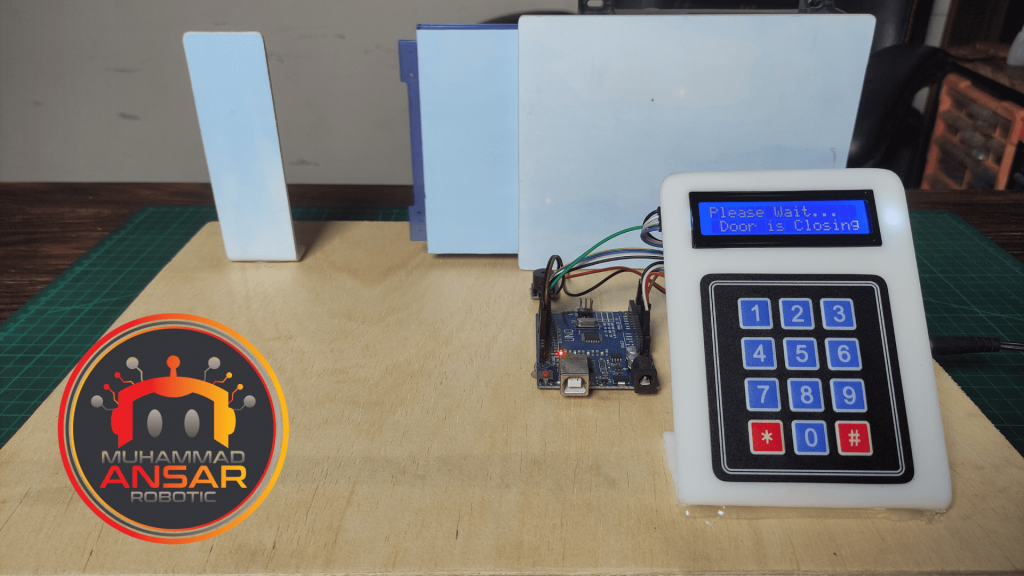
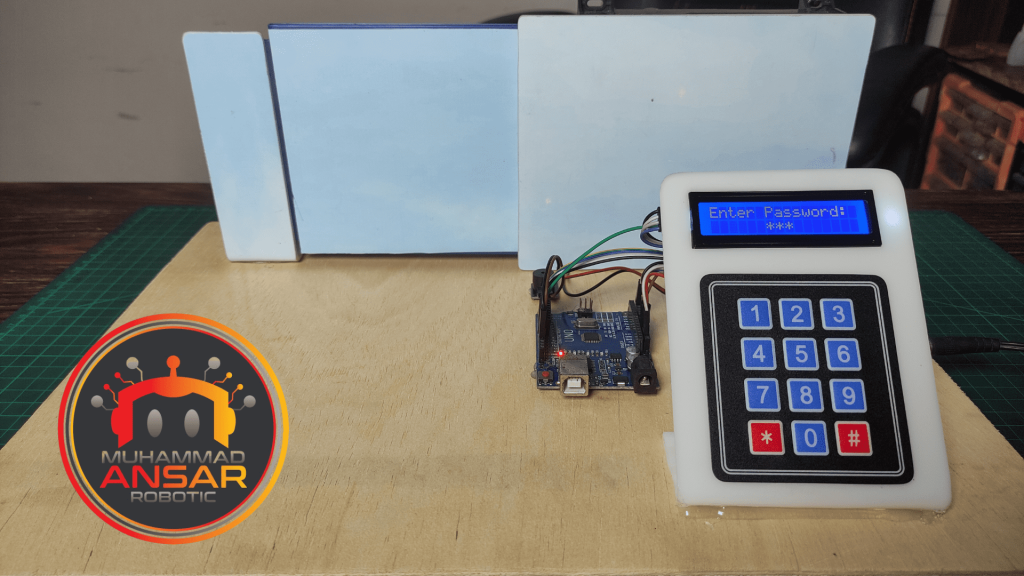
Hardware Testing
Conclusion
In conclusion, an easy and effective approach to improve security in your personal areas is using a Password-based Door Lock System that uses an Arduino and a Keypad. With easily accessible parts and our thorough instructions, you can build a sturdy, dependable, and reasonably priced door locking system. The included circuit schematic makes hardware setup easier, and the Proteus simulation assists you in making sure your design is solid. You will get a fully working Keypad Door Lock that may give you protection and peace of mind for your house or other areas when the hardware testing is accomplished. Thanks to the power of Arduino and creative electronics projects like this one, achieving security has never been simpler.


Leave a Reply