
Arduino Based Color Detector Using TCS230 | TCS3200 Color Sensor

Introduction
Color detection is an interesting area of technological application that has applications in art and design, automation, and quality control, among other domains. In this project, we’ll look at how to make a color detector out of an Arduino Uno, a 16×2 LCD display, and a TCS230/TCS3200 color sensor. This configuration will enable you to recognize and show the color of an object that is positioned in front of the sensor with accuracy. This blog demonstrates an accurate and efficient approach of detecting colors in the surroundings. MArobotics’ use of the TCS230 sensor and Arduino microcontroller provides an accessible and adaptable approach for applications including industrial automation to creative endeavors. This color detecting system enables automation, sorting, and interactive installations, which makes it an interesting and practical project at the crossroads of electronics and color sensing technology.
Components Required
- Solderless Breadboard
- Arduino UNO
- TCS230/TCS3200 Color Sensor
- 16×2 LCD Display
- 10k Variable Resistor
- 100R Resistor
- Male to Male Jumper Wires
- Male to Female Jumper Wires
- Hard Jumper Wire
- Battery Clip
- 9V Battery
Circuit Diagram
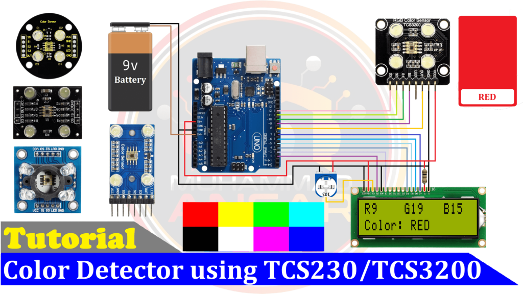
In order to power the complete system in this project, we’ve used a 9-volt battery. The Arduino Uno, which acts as the Color Detector’s brain, is the main element of the project. The values of red, green, and blue are shown in the first line of a 16×2 LCD display, while the detected color is shown in the second line. For best viewing, a 10k potentiometer controls the LCD’s contrast level. Anode pin 15 and cathode pin 16, where the cathode is linked directly to ground and anode is connected in series with a 100-ohm resistor to regulate backlighting, are responsible for the LCD’s backlighting. We have included the TCS3200 color sensor into the configuration in order to collect color data. The red, green, and blue readings that this sensor can provide. The system will determine and show the matching color based on these variables. It’s important to remember that TCS230 and TCS3200 share a common protocol, which permits component selection freedom. Pin 8 on the Arduino is connected to the “out” pin of the sensor, while pins S0 and S1 are connected to pins 9 and 10, respectively. Furthermore, pins 11 and 12 are linked to S2 and S3, respectively. The item being scanned is illuminated by four LEDs, which are detected by the TCS3200. The frequency of the reflected light fluctuates over the RGB spectrum. To define the color and allow for accurate color recognition, the system processes these frequencies.
Arduino IDE Code
#include <LiquidCrystal.h>
LiquidCrystal lcd(2, 3, 4, 5, 6, 7);
#define outPin 8
#define s0 9
#define s1 10
#define s2 11
#define s3 12
boolean DEBUG = true;
// Variables
int red, grn, blu;
String color ="";
long startTiming = 0;
long elapsedTime =0;
void setup(){
  Serial.begin(9600);

  pinMode(s0, OUTPUT);
  pinMode(s1, OUTPUT);
  pinMode(s2, OUTPUT);
  pinMode(s3, OUTPUT);
  pinMode(outPin, INPUT); //out from sensor becomes input to arduino
  // Setting frequency scaling to 100%
  digitalWrite(s0,HIGH);
  digitalWrite(s1,HIGH);
  lcd.begin(16, 2);
  lcd.clear();
  lcd.setCursor (3,0);
  lcd.print("Welcome To");
  lcd.setCursor (1,1);
  lcd.print("Color Detector");
  delay(2000);
  lcd.clear();
  startTiming = millis();
}
void loop(){
  getColor();

  if(DEBUG)printData();
  elapsedTime = millis()-startTiming;
  if (elapsedTime > 1000) {
     showDataLCD();
    startTiming = millis();
  }
}
/* read RGB components */
void readRGB(){
  red = 0, grn=0, blu=0;

  int n = 10;
  for (int i = 0; i < n; ++i){
    //read red component
    digitalWrite(s2, LOW);
    digitalWrite(s3, LOW);
    red = red + pulseIn(outPin, LOW);

   //read green component
    digitalWrite(s2, HIGH);
    digitalWrite(s3, HIGH);
    grn = grn + pulseIn(outPin, LOW);

   //let's read blue component
    digitalWrite(s2, LOW);
    digitalWrite(s3, HIGH);
    blu = blu + pulseIn(outPin, LOW);
  }
  red = red/n;
  grn = grn/n;
  blu = blu/n;
}
/***************************************************
* Showing captured data at Serial Monitor
****************************************************/
void printData(void){
  Serial.print("red= ");
  Serial.print(red);
  Serial.print("   green= ");
  Serial.print(grn);
  Serial.print("   blue= ");
  Serial.print(blu);
  Serial.print (" - ");
  Serial.print (color);
  Serial.println (" detected!");
}
///***************************************************
//* Showing capured data at LCD
//****************************************************/
void showDataLCD(void){
lcd.clear();
lcd.setCursor (0,0);
lcd.print("R");
lcd.print(red);
lcd.setCursor (6,0);
lcd.print("G");
lcd.print(grn);
lcd.setCursor (12,0);
lcd.print("B");
lcd.print(blu);
lcd.setCursor (0,1);
lcd.print("Color: ");
lcd.print(color);
}
void getColor(){
  readRGB();
     if(red>7  && red<11  && grn>17 && grn<23 && blu>13 && blu<18) color = "RED";
else if(red>17 && red<21  && grn>11 && grn<15 && blu>12 && blu<18) color = "GREEN";
else if(red>22 && red<28  && grn>11 && grn<16 && blu>6  && blu<10) color = "BLUE";
else if(red>4  && red<8   && grn>6  && grn<10 && blu>9  && blu<13) color = "YELLOW";
else if(red>5  && red<8   && grn>4  && grn<8  && blu>3  && blu<7)  color = "WHITE";
else if(red>28 && red<36  && grn>25 && grn<34 && blu>20 && blu<29) color = "BLACK";
else  color = "NO_COLOR";
}
Explanation
The “LiquidCrystal” library, which controls the 16×2 LCD, is first included in the code. It initializes the pins of the TCS3200 color sensor as well as the LCD (pins 2 through 7). The pin 8 of the Arduino is linked to the “out” pin of the color sensor, whereas pins 9 through 12 are designated for pins S0, S1, S2, and S3. RGB values are sent to the serial monitor by the code, which by default sets a “DEBUG” variable to “true”. You may keep it set to “true” if all you want the monitor to show is RGB values. Otherwise, make it “false.” The setup section initializes pins S0 through S3 for the color sensor and sets the serial monitor to a baud rate of 9600. In addition, the code clears the LCD, initializes it, and shows a message for two seconds. The “startTiming” variable contains the LCD’s startup time. The “getColor()” method is called by the code in the loop section. This function uses the RGB data it receives from the color sensor to define the color and then shows it on the LCD. The “DEBUG” variable determines whether or not this data is delivered to the serial monitor.
Every 1000 milliseconds, the “showDataLCD()” method is run in order to update and display RGB values and colors on the LCD. RGB values are obtained from the color sensor using the “readRGB()” method, and colors and RGB values are shown on the serial monitor using the “printData()” function. Conditional statements are used by the “getColor()” method to define colors depending on RGB values. To determine the color, for example, it compares the values of red, green, and blue. Then, when a certain condition is satisfied, it modifies the “color” variable. It is demonstrated how to modify the code to add more colors, such “black.” By designating a color variable and providing RGB value ranges, more colors may be added. The code upload procedure is finally described, with a focus on how crucial it is to calibrate the color sensor based on the ambient light levels in the area it would be utilized. With the use of RGB values for each hue and conditional adjustment, the hue Detector can precisely detect a large number of colors. The calibration procedure makes sure the color sensor can detect colors correctly and adjust to different lighting conditions.
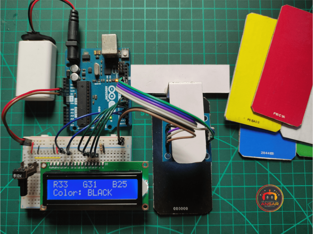
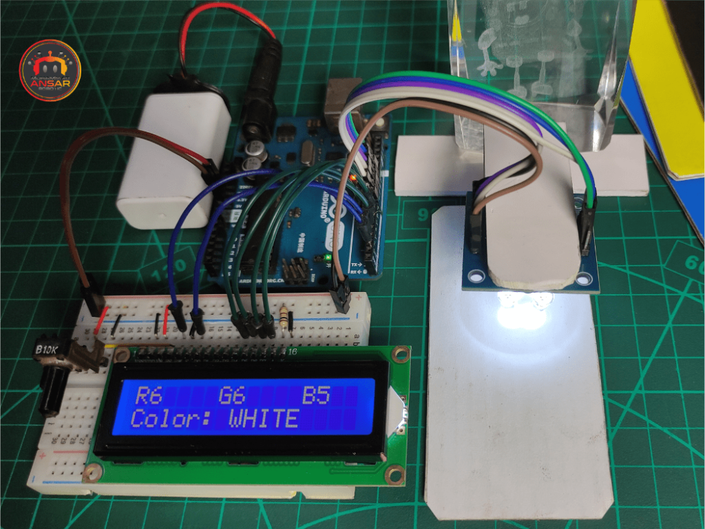
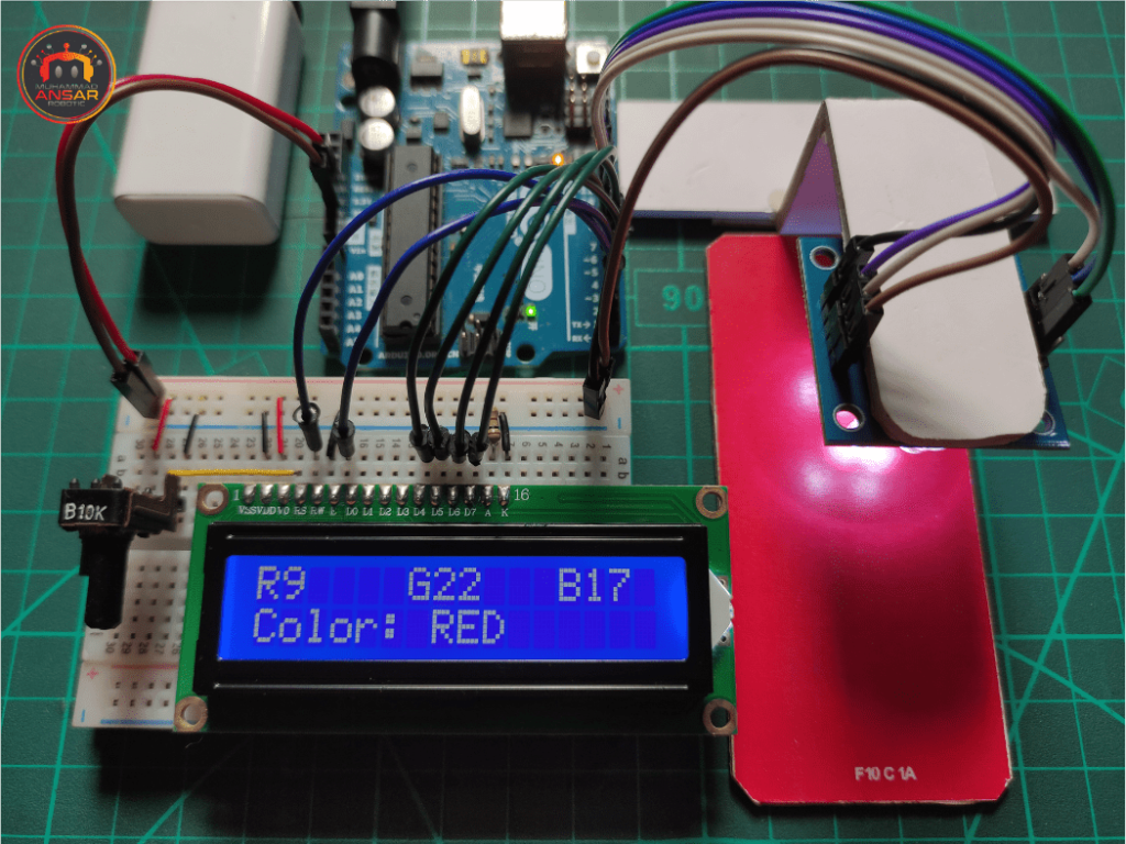
Hardware Testing
After connecting the Arduino to your computer and uploading the code, use the 9V battery to power the circuit. Make sure that all hardware connections are correct. Place a variety of colored items in front of the sensor to test the color detector. The detected color ought to appear on the LCD. It also shows the color code values in RGB.
Conclusion
In this project, we looked at how to make a color detector out of an Arduino Uno, a 16×2 LCD display, and a TCS230/TCS3200 color sensor. You may construct your own color detecting system, which has uses in automation, quality assurance, and artistic endeavors, by referring to the guidelines and code that are supplied. To find out how well your Color Detector can recognize and show colors, experiment with various items and colors. An excellent chance to learn about sensors, microcontrollers, and data representation using an LCD display is provided by this project.
3 responses to “Arduino Based Color Detector Using TCS230 | TCS3200 Color Sensor”

Sir please make a vedio on fake currency detecter by Arduino uno
Sir please make a vedio on fake currency detecter by Arduino uno with code
Now all is clear, many thanks for the information.


3 thoughts on “Arduino Based Color Detector Using TCS230 | TCS3200 Color Sensor”
 Krishna Mhetraskar says:
Sir please make a vedio on fake currency detecter by Arduino uno
- Krishna Mhetraskar says:
Sir please make a vedio on fake currency detecter by Arduino uno with code
Leave a Reply