
Automatic Door Opening System Using Arduino And PIR Sensor

Introduction
Automatic door opening systems are getting more and more common in a variety of settings, including residential and business buildings. Facilitation, safety, and savings on energy are provided by these systems. We will look at how to use an Arduino and a PIR (Passive Infrared) sensor to develop an automatic door opening system in this blog article. This project may be a useful addition to your house or place of business in addition to being entertaining and informative.
Components Required
- Vinyl Paper
- 3mm Acrylic Sheet
- Solderless Breadboard
- Arduino UNO
- 100R Resistor x 2
- Green LED
- Red LED
- Mini L298N Motor Driver
- DVD Room Gate (assuming you mean a DVD drive or optical drive)
- PIR Sensor
- Male to Male Jumper Wires
- Male to Female Jumper Wires
- Female DC Power Jack
- 5V 2Amp Power Adapter
Proteus Simulation
The built Arduino code is run at the start of the simulation to regulate the door’s functionality. Initially, the mechanism turns the motor clockwise for a certain amount of time to close the door. A timer LED illuminates to show the state of the door throughout this period. The Arduino immediately starts the motor in the opposite direction to open the door if the PIR sensor picks up motion. Concurrently, a green LED signals that the PIR sensor has detected motion. The green LED goes out when the PIR sensor detects nothing. The door begins to close automatically when the timer meets the predetermined time limit. Still, the mechanism is meant to react to movement. Thus, the timer resets to ensure that the door stays open if the PIR sensor detects motion even after it has stopped. Before beginning the actual construction, this simulation provides a useful and educational means of understanding the automated door opening system’s operation through a visual depiction.
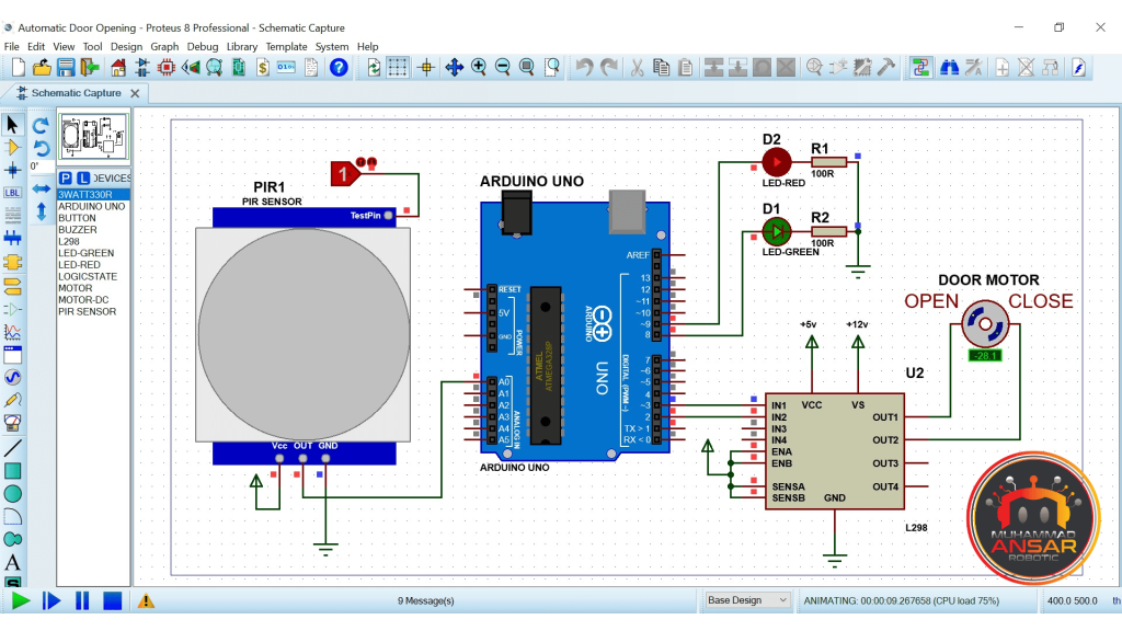
Circuit Diagram
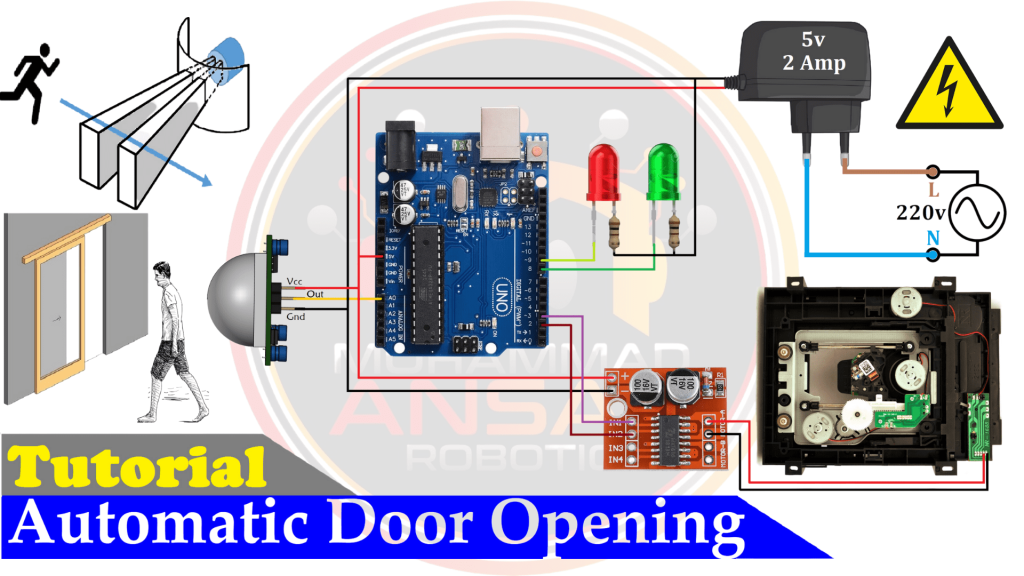
The Arduino Uno, the key component and system brain, is shown at the top of the circuit schematic. The motion-detecting PIR sensor is then included into the circuit. Furthermore, a noteworthy component is the L298N motor driver, which has two H-bridges for motor control. A DC motor that is attached to the motor driver—more precisely, motor A—allows the door to move. The door is a well designed DVD room that is opened and closed by a DC motor that is driven by the H-bridge. To effectively show system status, the circuit additionally includes two LEDs, each with a matching 100-ohm resistor. Additionally, the graphic details the power source, which uses a 220-volt supply. A 5-volt, 2-amp power adapter powers the Arduino Uno, PIR sensor, and motor driver. The smooth and effective operation of the system is guaranteed by this meticulous configuration. The video instruction then goes on to show how to physically construct and connect the hardware parts, turning the automated door opening system on, using the circuit diagram as a reference.
Arduino IDE Code
#define sensorPin A0 // choose the input pin (for PIR sensor)
#define G_led 8 // choose the pin for the Green Led
#define R_led 9 // choose the pin for the Red Led
#define in1 2
#define in2 3
int set_timer=5;
int sensor =0;
int seconds =0;
int flag=0;
long delay_Start;
void setup(){ // put your setup code here, to run once
Serial.begin(9600);// initialize serial communication at 9600 bits per second:
pinMode(sensorPin, INPUT); // declare sensor as input
pinMode(R_led,OUTPUT); // declare Red LED as output
pinMode(G_led,OUTPUT); // declare Green LED as output
pinMode(in1,OUTPUT);
pinMode(in2,OUTPUT);
digitalWrite(in1, LOW); // Door Open
digitalWrite(in2, HIGH);// Door Close
delay(2000); // Waiting for a while
digitalWrite(in1, LOW); // Door Open
digitalWrite(in2, LOW); // Door Close
}
void loop(){
sensor = digitalRead(sensorPin);
if(sensor==1){ // pin state change: 0 -> 1
Serial.println("Motion detected!");
digitalWrite(R_led, HIGH); // LED Turn On
digitalWrite(G_led, HIGH); // LED Turn On
if(flag==0){
digitalWrite(in1, HIGH);// Door Open
digitalWrite(in2, LOW); // Door Close
delay(2000); // Waiting for a while
digitalWrite(in1, LOW); // Door Open
digitalWrite(in2, LOW); // Door Close
}
seconds=0;
flag=1;
delay_Start = millis(); // set start time
}else{ // pin state change: 1 -> 0
Serial.println("Motion stopped!");
digitalWrite(G_led, LOW); // LED Turn Off.
}
if((flag==1) && (millis()- delay_Start) > 999){
seconds = seconds+1;
delay_Start = millis(); // set start time
}
if(seconds>set_timer){
digitalWrite(R_led, LOW); // LED Turn Off.
digitalWrite(in1, LOW); // Door Open
digitalWrite(in2, HIGH);// Door Close
delay(2000); // Waiting for a while
digitalWrite(in1, LOW); // Door Open
digitalWrite(in2, LOW); // Door Close
flag=0;
seconds=0;
}
delay(100);
}
Explanation
Pins 8 and 9 of the Arduino are used for the green and red LEDs, respectively, while the PIR sensor is attached to pin A0 for motion detection. The door’s DC motor is driven by the L298N motor driver, which is set up to be controlled by pins 2 and 3. The ‘set_timer’ variable, which controls how long the door stays open when motion is detected, is an important component of the code. Although it’s set to 5 seconds in this example, users are free to change this number to fit their needs. The code makes it very evident that the door opens and the timer LED is turned on for the predetermined amount of time when the PIR sensor detects motion. The door closes on its own after this amount of time if no more motion is detected. To regulate the actions of the system, variables like ‘sensor,”seconds,’ ‘flag,’ and ‘delay_Start’ are defined and initialized. The setup is described in more depth later in the code, where pin configuration, the serial connection rate, and the starting state of the door and LEDs are defined. Interestingly, the door closes for a mere 2000 milliseconds when the motor is momentarily turned on. This code continuously monitors the PIR sensor’s output in the ‘loop’ section. It writes ‘Motion detected’ on the serial monitor, turns on the green LED, sets the flag, and controls the motor to open the door when motion is detected. The commencement time is also recorded so that elapsed seconds may be tracked. It reports ‘Motion ceased,’ switches off the green LED, and keeps running the timer when the motion stops. The timer resets if the door stays open and motion is detected. The code activates the red LED and rotates the motor counterclockwise to close the door once the predetermined amount of time has passed. The code ends, waits 100 milliseconds, and then loops back.
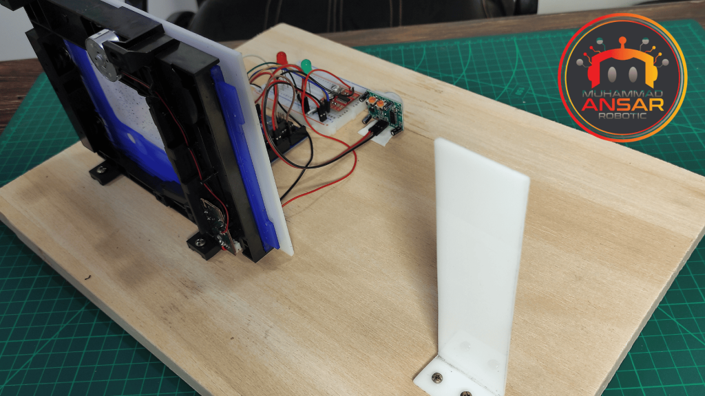
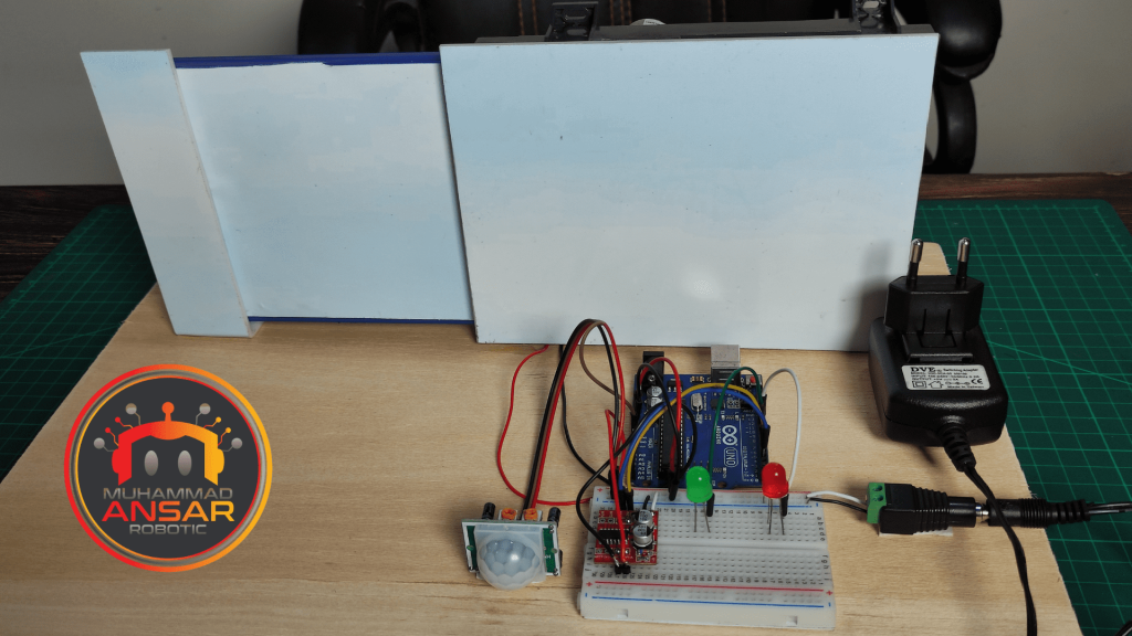
Hardware Testing
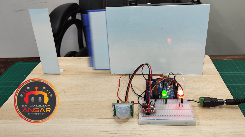
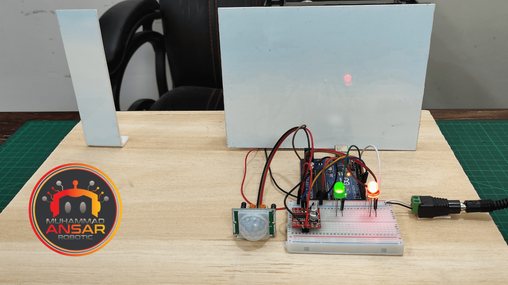
It’s time to test your hardware after you’ve uploaded the code to your Arduino. Verify that the motor driver can operate the DVD room gate and that the PIR sensor can detect motion. The system’s state should also be accurately displayed via the LEDs. To make sure everything functions as it should, this step is essential.
Conclusion
Using an Arduino and a PIR sensor to construct an automatic door opening system is not only an exciting technological experiment, but it’s also a workable way to improve convenience and security. You may create a working system that reacts to motion and opens doors automatically by using the previously specified components, building a sturdy circuit, and putting the Arduino code into practice. This project has a wide range of applications, from workplace automation to home security. Whether you want to increase accessibility, make your workstation more efficient, or create a hands-free doorway at home, you can customize this system to meet your unique needs.
3 responses to “Automatic Door Opening System Using Arduino And PIR Sensor”

the arduino ide code can it be the same when using a gsm module
Hello, this project is very interesting. How do I go about using a different motor, for instance, a sliding door that is 2 meters long? The current motor is too small and has limited travel. How can I program a more powerful motor for a longer 2-meter travel?
Thank you.
كيفية التحكم فى سرعة الموتور أثناء الغلق فى اخر المسافة


3 thoughts on “Automatic Door Opening System Using Arduino And PIR Sensor”
 mikar says:
the arduino ide code can it be the same when using a gsm module
- davy-vas says:
Hello, this project is very interesting. How do I go about using a different motor, for instance, a sliding door that is 2 meters long? The current motor is too small and has limited travel. How can I program a more powerful motor for a longer 2-meter travel?
Thank you.
- محمد سمير says:
كيفية التحكم فى سرعة الموتور أثناء الغلق فى اخر المسافة
Leave a Reply