
Automatic Fire Fighting Robot Using Arduino

Introduction
Emergency situations involving fires can be fatal and damaging, necessitating quick action and effective remedies. In this project, we’ll investigate how to use Arduino to build an automatic fire-fighting robot. This robot is a vital tool for fire safety and prevention as it can automatically identify and put out flames. This robot can recognize fires and react quickly to put them out by combining sensors, motors, and smart control.
Components Required
- 3mm Acrylic Sheet
- Solderless Breadboard
- 4 wheel robot car kit
- Arduino UNO
- Flame Sensor x 3
- L298 Motor Driver
- Mini Servo Motor SG90
- TIP-122 Transistor
- 1k Resistor
- 104pf Capacitor
- PVC Water pipe 8mm
- 12V DC Water Pump
- Water Tank
- Male to Male Jumper Wires
- Male to Female Jumper Wires
- Hard Jumper Wire
- Male Header
- On/Off Switch
- Female DC Power Jack
- 2S BMS 7.4V 3A Over Charge-Discharge Protection
- 18650 Battery Holder – 2 Cell
- 18650 Battery Cell 3.7V x 2
- 9Volt 1.5Amp Power Adapter
Circuit Diagram
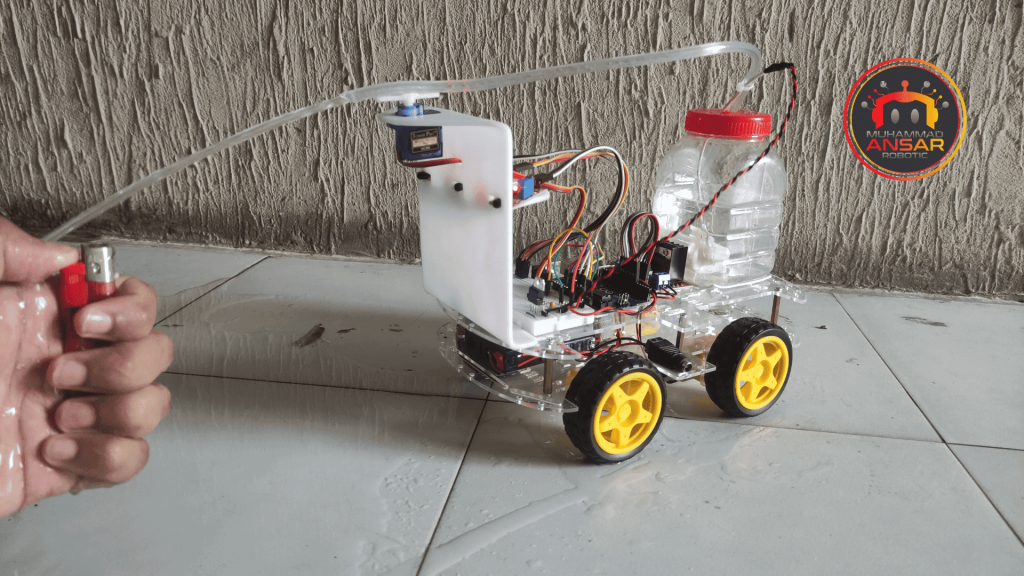
The robot’s power supply is made up of two 3.7 volt batteries that are linked in series to generate a total voltage of 8.4 volts. These batteries are charged safely thanks to the use of a Battery Management System (BMS) built for two cells. The lifetime and safety of the batteries are guaranteed by the BMS, which is crucial for avoiding overcharge and discharge problems. A power switch that enables the user to quickly and easily turn the robot off and on again is also included in the power supply design, along with a female DC connector for a 9-volt adaptor. With this setup, the robot’s power supply options are expanded as it can run directly off of an adapter or batteries. The firefighting robot’s brains are provided by an Arduino UNO, which acts as the microprocessor at its heart. It analyzes the information received from the flame sensors and manages a number of different parts. Three flame sensors on the robot are arranged in a smart manner to detect flames from various angles. There are three sensors: one on the back, one on the front, and one on the left. These sensors are essential for determining whether flames are present. The robot’s mobility is managed using a small servo motor, the SG90. It gives the robot the ability to adjust its position and react to flames that are detected.
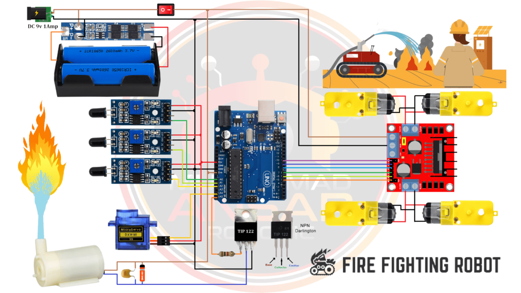
A DC water pump is used for putting out flames. A filter capacitor and a diode are connected in parallel with the water pump’s power supply to guarantee correct operation and safety. This diode shields the pump and aids in preventing reverse biasing. To control the water pump, the system uses an NPN transistor, the TIP 122, in conjunction with a 1k ohm biasing resistor. This transistor allows the pump to be turned on or off as needed by controlling the current flowing to it. Robot movement is managed by use of an L298 motor driver. It works in conjunction with the Arduino to operate the DC motors in both clockwise and counterclockwise directions. For motor control, the necessary pins on the Arduino are linked to the corresponding pins on the L298 motor driver. The arrangement also includes a power connection to supply electricity to the robot as a whole. By connecting the power connection to the battery, you can make sure the robot gets the energy it needs to function. The L298 motor driver’s OUT1, OUT2, OUT3, and OUT4 ports are where the motors are linked, enabling control over the left and rear motors.
Arduino IDE Code
#define enA 10//Enable1 L298 Pin enA
#define in1 9 //Motor1  L298 Pin in1
#define in2 8 //Motor1  L298 Pin in2
#define in3 7 //Motor2  L298 Pin in3
#define in4 6 //Motor2  L298 Pin in4
#define enB 5 //Enable2 L298 Pin enB
#define ir_R A0
#define ir_F A1
#define ir_L A2
#define servo A4
#define pump A5
int Speed = 160; // Write The Duty Cycle 0 to 255 Enable for Motor Speed
int s1, s2, s3;
void setup(){ // put your setup code here, to run once
Serial.begin(9600); // start serial communication at 9600bps
pinMode(ir_R, INPUT);// declare fire sensor pin as input
pinMode(ir_F, INPUT);// declare fire sensor pin as input
pinMode(ir_L, INPUT);// declare fire sensor pin as input
pinMode(enA, OUTPUT); // declare as output for L298 Pin enA
pinMode(in1, OUTPUT); // declare as output for L298 Pin in1
pinMode(in2, OUTPUT); // declare as output for L298 Pin in2
pinMode(in3, OUTPUT); // declare as output for L298 Pin in3
pinMode(in4, OUTPUT); // declare as output for L298 Pin in4
pinMode(enB, OUTPUT); // declare as output for L298 Pin enB
pinMode(servo, OUTPUT);
pinMode(pump, OUTPUT);
 for (int angle = 90; angle <= 140; angle += 5)  {
   servoPulse(servo, angle);  }
 for (int angle = 140; angle >= 40; angle -= 5)  {
   servoPulse(servo, angle);  }
 for (int angle = 40; angle <= 95; angle += 5)  {
   servoPulse(servo, angle);  }
analogWrite(enA, Speed); // Write The Duty Cycle 0 to 255 Enable Pin A for Motor1 Speed
analogWrite(enB, Speed); // Write The Duty Cycle 0 to 255 Enable Pin B for Motor2 Speed

delay(500);
}
void loop(){
s1 = analogRead(ir_R);
s2 = analogRead(ir_F);
s3 = analogRead(ir_L);

//=============================================================
//                         Auto Control
//=============================================================
Serial.print(s1);
Serial.print("\t");
Serial.print(s2);
Serial.print("\t");
Serial.println(s3);
delay(50);
if(s1<250){
Stop();
digitalWrite(pump, 1);
for(int angle = 90; angle >= 40; angle -= 3){
servoPulse(servo, angle);
}
for(int angle = 40; angle <= 90; angle += 3){
servoPulse(servo, angle);
}
}
else if(s2<350){
Stop();
digitalWrite(pump, 1);
for(int angle = 90; angle <= 140; angle += 3){
servoPulse(servo, angle);
}
for(int angle = 140; angle >= 40; angle -= 3){
servoPulse(servo, angle);
}
for(int angle = 40; angle <= 90; angle += 3){
servoPulse(servo, angle);
 }
}
else if(s3<250){
Stop();
digitalWrite(pump, 1);
for(int angle = 90; angle <= 140; angle += 3){
servoPulse(servo, angle);
}
for(int angle = 140; angle >= 90; angle -= 3){
servoPulse(servo, angle);
}
}
else if(s1>=251 && s1<=700){
digitalWrite(pump, 0);
backword();
delay(100);
turnRight();
delay(200);
}
else if(s2>=251 && s2<=800){
digitalWrite(pump, 0);
forword();
}
else if(s3>=251 && s3<=700){
digitalWrite(pump, 0);
backword();
delay(100);
turnLeft();
delay(200);
}else{
digitalWrite(pump, 0);
Stop();
}
delay(10);
}
void servoPulse (int pin, int angle){
int pwm = (angle*11) + 500;      // Convert angle to microseconds
 digitalWrite(pin, HIGH);
 delayMicroseconds(pwm);
 digitalWrite(pin, LOW);
 delay(50);                   // Refresh cycle of servo
}
void forword(){  //forword
digitalWrite(in1, HIGH); //Right Motor forword Pin
digitalWrite(in2, LOW);  //Right Motor backword Pin
digitalWrite(in3, LOW);  //Left Motor backword Pin
digitalWrite(in4, HIGH); //Left Motor forword Pin
}
void backword(){ //backword
digitalWrite(in1, LOW);  //Right Motor forword Pin
digitalWrite(in2, HIGH); //Right Motor backword Pin
digitalWrite(in3, HIGH); //Left Motor backword Pin
digitalWrite(in4, LOW);  //Left Motor forword Pin
}
void turnRight(){ //turnRight
digitalWrite(in1, LOW);  //Right Motor forword Pin
digitalWrite(in2, HIGH); //Right Motor backword Pin
digitalWrite(in3, LOW);  //Left Motor backword Pin
digitalWrite(in4, HIGH); //Left Motor forword Pin
}
void turnLeft(){ //turnLeft
digitalWrite(in1, HIGH); //Right Motor forword Pin
digitalWrite(in2, LOW);  //Right Motor backword Pin
digitalWrite(in3, HIGH); //Left Motor backword Pin
digitalWrite(in4, LOW);  //Left Motor forword Pin
}
void Stop(){ //stop
digitalWrite(in1, LOW); //Right Motor forword Pin
digitalWrite(in2, LOW); //Right Motor backword Pin
digitalWrite(in3, LOW); //Left Motor backword Pin
digitalWrite(in4, LOW); //Left Motor forword Pin
}
Explanation
The pins that link to the L298 motor driver, which drives the robot’s movement, are initially initialized in this Arduino code. These pins are essential for controlling how the robot moves, giving it the ability to turn, move forward, and travel backward. The code initializes three pins for flame sensors after the motor driver pins. Flame sensors are essential to this project since they allow the robot to recognize when flames are present. To ensure thorough fire detection, three sensors are placed: one on the left, one in front, and one at the back. One of the pins is also used to initialize the servo motor, which regulates the robot’s orientation. For a precise reaction, it enables the robot to rotate and align itself with the fire source that has been detected. There’s also a pin for the water pump, which is an essential part of putting out flames.
In Auto Control, the first part of the code involves printing sensor readings to the Serial Monitor. It then checks conditions based on these readings to determine the actions to be taken. The actions include controlling a pump, adjusting the angle of a servo motor, and directing the movement of motors. For instance, if the reading from sensor s1 is less than 250, it initiates a series of movements with the servo motor and activates a pump. Similar logic is applied for different sensor conditions, controlling the pump and servo motor to achieve specific sequences of actions such as forward movement, backward movement, turning left, and turning right. The motor control functions (forword, backword, turnRight, turnLeft, Stop) indicate the corresponding motor movements. The servoPulse function is responsible for controlling the servo motor’s angle based on the desired position, and the delay in the servoPulse function establishes a refresh cycle for the servo.
When this pump is turned on, water is released to put out the flames. “Speed,” a crucial variable in the code, establishes the duty cycle. The robot’s speed is largely determined by its duty cycle. Lower speed is selected in an autonomous robot so that it can respond to fire crises with more accuracy. The duty cycle allows for precise control over the robot’s speed, with a minimum value of 0 and a maximum value of 255. Now that the code has been set up to manage the robot’s hardware, it can be uploaded and run on the Arduino board. This may be accomplished by selecting the relevant board, usually the “Arduino UNO,” from the “Tools” menu, and then the appropriate COM port connected to the Arduino. By selecting the “Upload” button, you may upload the code to the board when these settings are complete. The code will be running on the Arduino after a successful upload, allowing the robot to recognize and react to fire hazards on its own. Now that the code is in charge of the robot’s motions and activities, fire safety has an effective and maybe life-saving answer.
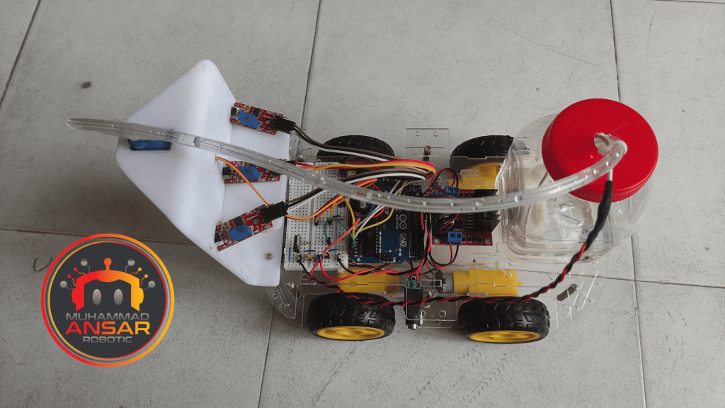
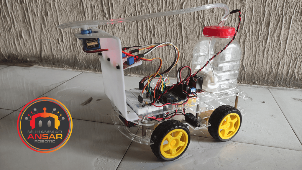
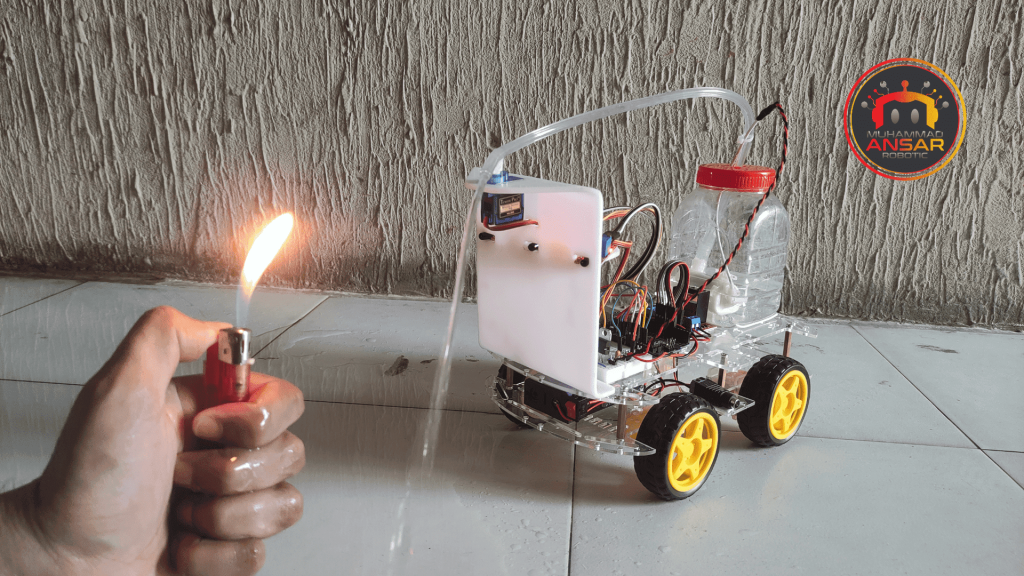
Hardware Testing
Put the robot together in accordance with the schematic and program the Arduino board with the code. Employing one of the flame sensors, simulate a fire to test the robot’s capabilities. Watch the robot’s actions to see if it accurately locates the fire, moves toward it, then turns on the water pump to put out the flames.
Conclusion
An important invention that can greatly improve disaster and fire safety is the Automatic Fire-Fighting Robot. It uses a variety of parts, including as motors, Arduino control, and flame sensors, to identify and put out flames on its own. By use of Proteus simulations and thorough hardware testing, the robot’s performance may be adjusted to provide optimal performance in real-world scenarios. This study shows how technology may be used to protect people and property while providing a workable answer for dealing with fire crises.
17 responses to “Automatic Fire Fighting Robot Using Arduino”

What do you mean by servo pulse, I tried uploading it but it says that it is invalid
contact my whatsapps number
Hello sir is there any changes in your code ? Can you please send it on my email : ashliejane01@gmail.com
Bro please send your mail I’d please
Assalamualaikum
Sir code showing error
Mail me new code pleasewa alaikum assalam
kia error dekha raha hyAssalamualaikum
Sir compilation error dikha Raha hai
Sir kya kare 24th ko mujhe dikhana hai sir please help
Is this for real
yes it’s real
Assalammualikum sir malaysia can buy this project?
wa alaikum assalam
where are you from?Im from Malaysia can I buy?
Hurrah, that’s what I was exploring for, what
a stuff! present here at this blog, thanks admin of this website.welcome
Keep up the amazing work!
thank you


17 thoughts on “Automatic Fire Fighting Robot Using Arduino”
 1234 says:
What do you mean by servo pulse, I tried uploading it but it says that it is invalid
- Ashlie Jane Balidio says:
Hello sir is there any changes in your code ? Can you please send it on my email : ashliejane01@gmail.com
- Mohamed shafi says:
Bro please send your mail I’d please
- Shaikh Ataur Rehman says:
Assalamualaikum
Sir code showing error
Mail me new code please- Shaikh Ataur Rehman says:
Assalamualaikum
Sir compilation error dikha Raha hai
Sir kya kare 24th ko mujhe dikhana hai sir please help
- Rizal says:
Is this for real
- ali says:
Assalammualikum sir malaysia can buy this project?
- Ali says:
Im from Malaysia can I buy?
Hurrah, that’s what I was exploring for, what
a stuff! present here at this blog, thanks admin of this website.
Leave a Reply