
Third Eye for The Blind Person using Arduino and Ultrasonic Sensor

Introduction
The “Third Eye for the Blind Person” project by MArobotics is an innovative use of Arduino and Ultrasonic Sensor technology to improve the mobility and freedom of visually impaired people. This project uses an ultrasonic sensor to identify obstructions in the user’s direction, and the Arduino microcontroller interprets the data to offer real-time feedback. The device is intended to notify the user to barriers by haptic or aural signals, providing a practical and economical solution to assist visually impaired persons in navigating their environment with increased confidence and safety. The MArobotics project shows the effective use of modern technology to tackle real-world difficulties while enhancing the standard of life for people with visual impairments. We work to improve the lives of people who have difficulty seeing in a world full with technology developments.
Components Required
- Veroboard (6cm x 8cm)
- Arduino Nano
- HC-sr04 Ultrasonic Sensor
- Push Buttons (x3)
- 1k Resistor
- C945 NPN Transistor
- 4148 Diode
- 0.1uF Capacitor
- Vibrator Motor
- Buzzer
- Hard Jumper Wires
- Velcro Tape
- Slide Switch (On/Off)
- 3.7V Lithium Battery Charger Board (Charging/Boost Converter)
- 3.7V Lithium Battery
Proteus Simulation
A thorough example of the device’s operation in the Proteus 8 environment may be seen in the simulation file that is given for the Smart Blind Stick project. An Arduino UNO, a virtual terminal, push buttons, a buzzer, an NPN transistor, and an HC-SR04 ultrasonic sensor are all used in the simulation. Monitoring and displaying the distance values found by the ultrasonic sensor on the serial interface is the function of the virtual terminal. This is essential to comprehending how the gadget engages with its environment. An Arduino code is included to run the simulation. The Smart Blind Stick’s behavior is managed by this code. Open it in the Arduino IDE. After selecting the Arduino UNO board from the “Tools” menu, the code is built, and the hex file’s address is copied. The Proteus simulation may then be run by pasting the hex file location into it. The virtual terminal starts to output centimeter-based distance data as soon as the simulation starts. The values below are required for the device to function. Both the buzzer and the vibrator sound when the distance falls below 100 cm.
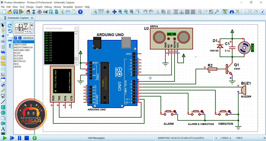
When the distance gets closer to zero, the vibrator and buzzer both get more intense and start blaring. They both stay on when the distance is less than 20 cm. To regulate the rate of vibration and beeping, the gadget dynamically modifies the on and off periods.
Push buttons allow users to select from a variety of operating modes. Only the alarm is activated by the first button, the alarm and vibrator are activated by the second, and the vibrator is the only thing activated by the third button. Both the buzzer and the vibrator stop working when the distance value goes above 100 cm. This thorough simulation is an essential part of the project’s development and testing process as it aids in comprehending the Smart Blind Stick’s operation.
Circuit Diagram
A 2000mAh, 3.7-volt battery is shown at the top of the circuit schematic as the Smart Blind Stick’s main power supply. A 5-volt, 1-ampere power bank kit is incorporated into the circuit to control power distribution and provide a constant voltage. In order to save energy while not in use, users may turn the gadget on and off with the provided power switch. The microcontroller in the center of the circuit is an Arduino Nano (in the circuit schematic, an Arduino UNO was utilized in the simulation). It’s crucial to remember that the code may be uploaded to any board because they both use the same Atmega328 microcontroller.
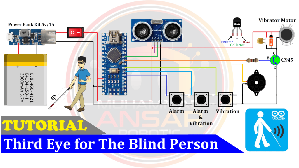
The HC-SR04 ultrasonic sensor monitors the gap between the user and obstacles by using sound waves to detect them. Three push buttons on the circuit allow users to choose between several operating modes. To give the user aural feedback, a buzzer is integrated. An NPN transistor and a 1-kilo ohm biasing resistor are utilized to regulate the vibrator motor. The microcontroller can turn the motor on and off as needed thanks to this combination. The purpose of the vibrator motor is to give the user haptic feedback. It increases the individual’s awareness of potential roadblocks. To control voltage spikes and guarantee steady motor performance, a 4148 diode and a filter capacitor with a capacitance of 1 microfarad are added into the circuit.
Arduino IDE Code
#define button1 2 // this button use for only Alarm mode
#define button2 3 // this button use for Alarm & Vibrator mode
#define button3 4 // this button use for only Vibrator mode
#define buzzer 5 // this pin use for Alarm
#define motor  6 // this pin use for Vibrator Motor
#define echopin 7 // echo pin
#define trigpin 8 // Trigger pin
int Alarm=1, Vibrator=1;
int cm; // Duration used to calculate distance
void setup(){ // put your setup code here, to run once
Serial.begin(9600);// initialize serial communication at 9600 bits per second:
pinMode(button1, INPUT_PULLUP);
pinMode(button2, INPUT_PULLUP);
pinMode(button3, INPUT_PULLUP);
pinMode(buzzer, OUTPUT); //declare buzzer as output
pinMode(motor, OUTPUT); //declare vibrator Motor as output
pinMode(trigpin, OUTPUT); // declare ultrasonic sensor Echo pin as input
pinMode(echopin, INPUT);  // declare ultrasonic sensor Trigger pin as Output
delay(100);
}

void loop(){
if(digitalRead(button1)==0) Alarm=1, Vibrator=0; //only Alarm mode
if(digitalRead(button2)==0) Alarm=1, Vibrator=1; //Alarm & Vibrator mode
if(digitalRead(button3)==0) Alarm=0, Vibrator=1; //only Vibrator mode
// Write a pulse to the HC-SR04 Trigger Pin
digitalWrite(trigpin, LOW);
delayMicroseconds(2);
digitalWrite(trigpin, HIGH);
delayMicroseconds(10);
// Measure the response from the HC-SR04 Echo Pin
long ultra_time = pulseIn (echopin, HIGH);
  // Determine distance from duration
  // Use 343 metres per second as speed of sound
cm =  ultra_time / 29 / 2;
Serial.print("cm:");Serial.println(cm);
if(cm>=20 && cm<=100){
int d = map(cm, 20, 100, 20, 2000);
if(Alarm==1)digitalWrite(buzzer, HIGH);   // Turn on Buzzer
if(Vibrator==1)digitalWrite(motor, HIGH); // Turn on Vibrator
delay(100);
digitalWrite(buzzer, LOW); // Turn off Buzzer
digitalWrite(motor, LOW);  // Turn off Vibrator
delay(d);
}
if(cm<20){
if(Alarm==1)digitalWrite(buzzer, HIGH);   // Turn on Buzzer
if(Vibrator==1)digitalWrite(motor, HIGH); // Turn on Vibrator
}
if(cm>100){
digitalWrite(buzzer, LOW); // Turn off Buzzer
digitalWrite(motor, LOW);  // Turn off Vibrator
}
delay(10);
}
Explanation
Pins for different components are initialized at the start of the programming. Pins 5, 6, and 7 are utilized for the buzzer and vibrator motor, respectively, and pins 2, 3, and 4 are assigned to the three push buttons. Two pins are needed for the ultrasonic sensor: pin 7 is for the echo pin, and pin 8 is for the trigger pin. Furthermore, the vibrator and alarm variables are initialized to 1, meaning that both features are immediately turned on. The serial communication is started at a baud rate of 9600 in the setup function. This is crucial for troubleshooting and performance monitoring of the device. The buzzer and motor pins are in output mode, the push buttons are in input mode, the trigger pin is setup as an output, and the echo pin has been configured as an input. The code first enters a 100 millisecond pause before moving on to the main loop. The gadget runs continually while it is in the loop function. It begins by interpreting the push buttons’ digital states. Users can choose the operational mode by pressing a button, which sets its status to 0.
>>Pressing the first button causes the vibrator to be turned off (vibrator variable set to 0) and the alarm to be activated (alarm variable set to 1).
>>Pressing the second button activates the vibrator and alarm (both variables are set to 1).
>>Pressing the third button activates the vibrator (vibrator variable set to 1) and disables the alert (alarm variable set to 0).
The code then uses the ultrasonic sensor’s trigger pin to transmit a 40 kHz pulse, and then uses the echo response time to determine the distance. The serial monitor shows this distance measurement.
The algorithm then maps the distance value to an equivalent mapped value, enabling dynamic feedback intensity modification in response to distance variations. If the vibrator and alarm variables are set to 1, then the buzzer and motor pins are both set to HIGH. A component is not enabled if any of them is set to 0. The buzzer and motor’s on and off periods are controlled by the code, which produces different feedback depending on the distance value. Faster and more powerful feedback results from a decreasing off time as the distance lowers. Lastly, regardless of the status of the variables, the alert and vibrator sound if the distance falls below 20 cm. The programming makes sure the gadget keeps its functionality and safety while working in accordance with user wishes.
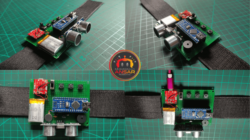
Hardware Testing
Make sure all the connections are made correctly, then double-check them. Testing comes next once the gear has been assembled. Turn on the gadget and watch how it acts. Ascertain that the vibrator motor and buzzer deliver the user the proper feedback and that the ultrasonic sensor correctly identifies impediments.
Conclusion
The Smart Blind Stick is more than simply a device; it’s evidence of how technology can improve people’s lives. The HC-sr04 Ultrasonic Sensor and an Arduino Nano are used in this gadget to provide vision impaired people with improved navigational skills. Projects like this serve as a reminder that innovation has the power to build a more just and inclusive society as we continue to investigate the relationship between technology and accessibility. In that regard, the Smart Blind Stick is a big step forward, providing more safety and freedom to those who most need it.
One response to “Third Eye for The Blind Person using Arduino and Ultrasonic Sensor”

I want to buy it


Leave a Reply