
Car Parking System Using Arduino And IR Sensor

Introduction
It’s more crucial than ever to park your automobile efficiently in the fast-paced world of today. With the development of technology, we can now come up with clever methods to deal with this problem. In this project, we are going to study the construction of an Arduino-based car parking system with IR sensors. With the aid of this technology, parking your automobile will be simple and perfectly aligned within the parking place. We will guide you through the parts and procedures needed to build this ground-breaking system. MArobotics develops a smart “Car Parking System” that uses Arduino and infrared sensors to optimize parking management. This novel invention uses infrared (IR) sensors to identify the presence of automobiles in parking lots. Using Arduino’s capabilities, the system interprets sensor data to assess parking availability and sends real-time updates to users. The MArobotics Car Parking System not only streamlines the parking procedure but also improves efficiency by reducing search time for available spots, resulting in a better and more structured approach to urban parking difficulties.
Components Required
- Solderless Breadboard
- Arduino UNO
- 2x IR Sensor
- Servo Motor SG-90
- 16×2 LCD Display
- 100R Resistor
- 4.7k Resistor
- 1k Resistor
- Male to Male Jumper Wires
- 2 Cell 18650 Battery Holder
- 2x 3.7V 18650 Battery Cells
- Power On/Off Switch
Proteus Simulation
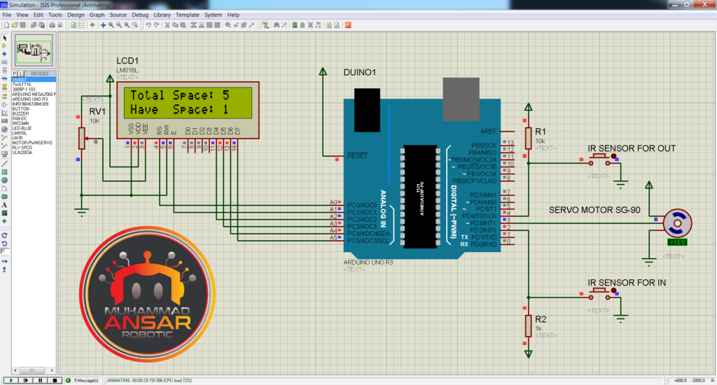
The core control unit of the project is an Arduino Uno, together with a 16×2 LCD display, two push buttons (which serve as IR sensors in the simulation), and an SG-90 servo motor. The push buttons indicate whether or not there are automobiles in the parking spots. The Arduino Uno’s uploaded code is intended to resemble the operations of an actual parking system. The total number of parking spots and the number of spaces that are available are displayed using the LCD. The “Have Space” value drops and the servo motor moves to open the parking barrier when a car passes the first “IR sensor” (simulated by a push button). Upon the vehicle leaving the second “IR sensor,” the barrier closes once more, and the value of “Have Space” rises. The way the method works is that it shows how the “Have Space” value rises and falls with each automobile that enters and leaves the parking lot. The parking system is efficient in its management of spots; when every place is taken, an LCD notification stating “Sorry, no space available” appears.
Circuit Diagram
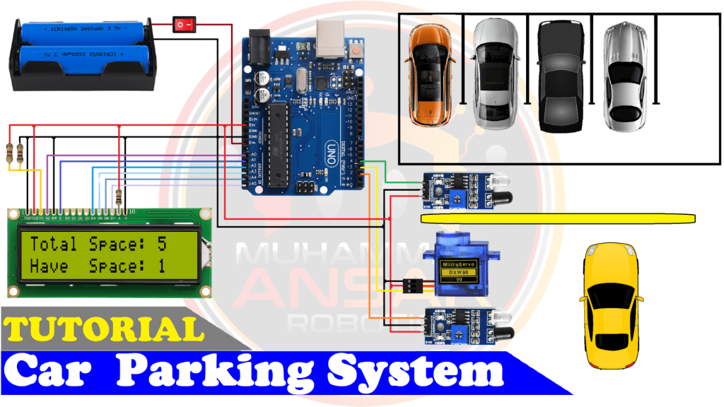
The project’s power source is a 7.4-volt battery, and an easy-to-use power on/off switch makes controlling the system’s power supply simple. The Arduino Uno is the central component of the system; it processes data from the infrared sensors, moves the servo motor, and controls the LCD display. The 16×2 LCD panel is used to show crucial data on the availability of parking spaces. The “Total Space” variable is displayed on the first line of the LCD, while the “Have Space” variable is displayed on the second line. To do this, use a 4.7-kilohm resistor linked to the +5 volt supply and a 1-kilohm resistor connected to ground. Furthermore, pin 15 and pin 16, the LCD’s backlight pins—pin 15 being the anode and pin 16 the cathode—are described. A 100-ohm resistor is connected to pin 15 and the +5 volt supply, while pin 16 is connected to the ground. A pair of infrared sensors is essential to the functioning of the device. Pin 2 of the Arduino Uno is linked to the first infrared sensor, while pin 4 is connected to the second infrared sensor. The presence of automobiles entering and leaving the parking space is detected by these sensors, which are essential. The Arduino Uno’s pin 3 is used to power a servo motor. The parking barrier is under the direction of the servo motor, which makes sure that it opens and shuts in response to the input from the infrared sensors.
Arduino IDE Code
#include <LiquidCrystal.h>// initialize the library with the numbers of the interface pins
LiquidCrystal lcd(A0, A1, A2, A3, A4, A5);
#include <Servo.h> //includes the servo library
Servo myservo1;
int ir_s1 = 2;
int ir_s2 = 4;
int Total = 5;
int Space;
int flag1 = 0;
int flag2 = 0;
void setup() {
pinMode(ir_s1, INPUT);
pinMode(ir_s2, INPUT);

myservo1.attach(3);
myservo1.write(100);
lcd.begin(16, 2);
lcd.setCursor (0,0);
lcd.print("  Car  Parking  ");
lcd.setCursor (0,1);
lcd.print("     System     ");
delay (2000);
lcd.clear();
Space = Total;
}
void loop(){
if(digitalRead (ir_s1) == LOW && flag1==0){
if(Space>0){flag1=1;
if(flag2==0){myservo1.write(0); Space = Space-1;}
}else{
lcd.setCursor (0,0);
lcd.print(" Sorry not Space ");
lcd.setCursor (0,1);
lcd.print("    Available    ");
delay (1000);
lcd.clear();
}
}
if(digitalRead (ir_s2) == LOW && flag2==0){flag2=1;
if(flag1==0){myservo1.write(0); Space = Space+1;}
}
if(flag1==1 && flag2==1){
delay (1000);
myservo1.write(100);
flag1=0, flag2=0;
}
lcd.setCursor (0,0);
lcd.print("Total Space: ");
lcd.print(Total);
lcd.setCursor (0,1);
lcd.print("Have  Space: ");
lcd.print(Space);
}
Explanation
Importing the “LiquidCrystal.h” library at the beginning of the code is necessary in order to communicate with the 16×2 LCD screen. After initializing the LCD pins as A0, A1, A2, A3, A4, and A5, the “Servo.h” library is included to allow servo motor control. The IR sensors are connected to pins 2 and 4 of the Arduino Uno, and the servo motor is initialized with the name “myservo1.”
The first thing the software does is define the total number of parking spots, which in this example is five. If more places are required, they may be added later. Together with two flags, “flag1” and “flag2,” both initially set to 0, the variable “space” is initialized. The servo motor (‘myservo1′) is connected to pin 3 and the IR sensors are set up in INPUT mode in the “setup()” method. When the barrier is closed, the servo motor’s starting setting of 100 degrees is reached. The “Car Parking System” message is then displayed on the LCD display for the first two seconds before being cleared. The entire value of parking spaces is assigned to the’space’ variable. The “loop()” function is the central component of the code. The first IR sensor is read first. It opens the barrier if the sensor detects LOW, which indicates the presence of an automobile, and ‘flag1′ is 0 (which indicates that the barrier is closed). When’space’ is larger than 0 and there is a parking spot available, the barrier opens, ‘flag1’ is set to 1, and ‘flag2′ is checked. The servo motor advances to 0 degrees (barrier open) and’space’ reduces by 1 if ‘flag2’ is also 0. The software shows “Sorry not Space Available” on the LCD if there are no parking spaces available. Next, the second IR sensor is read by the code. It sets ‘flag2’ to 1 if the sensor detects LOW and ‘flag2′ is 0. The barrier opens and’space’ rises by one if ‘flag1’ is 0. The automobile entry and egress is efficiently managed by this procedure. Before closing the barrier by turning the servo motor to 100 degrees, the code adds a 1-second delay when an automobile passes both IR sensors and “flag1” and “flag2” become 1. Following that, both flags are reset to 0, reactivating both IR sensors. The LCD gives consumers access to real-time information by showing the overall number of parking spaces as well as the available spaces. After the code has been clarified, the Arduino IDE may be used to upload it to the Arduino Uno.
Hardware Testing
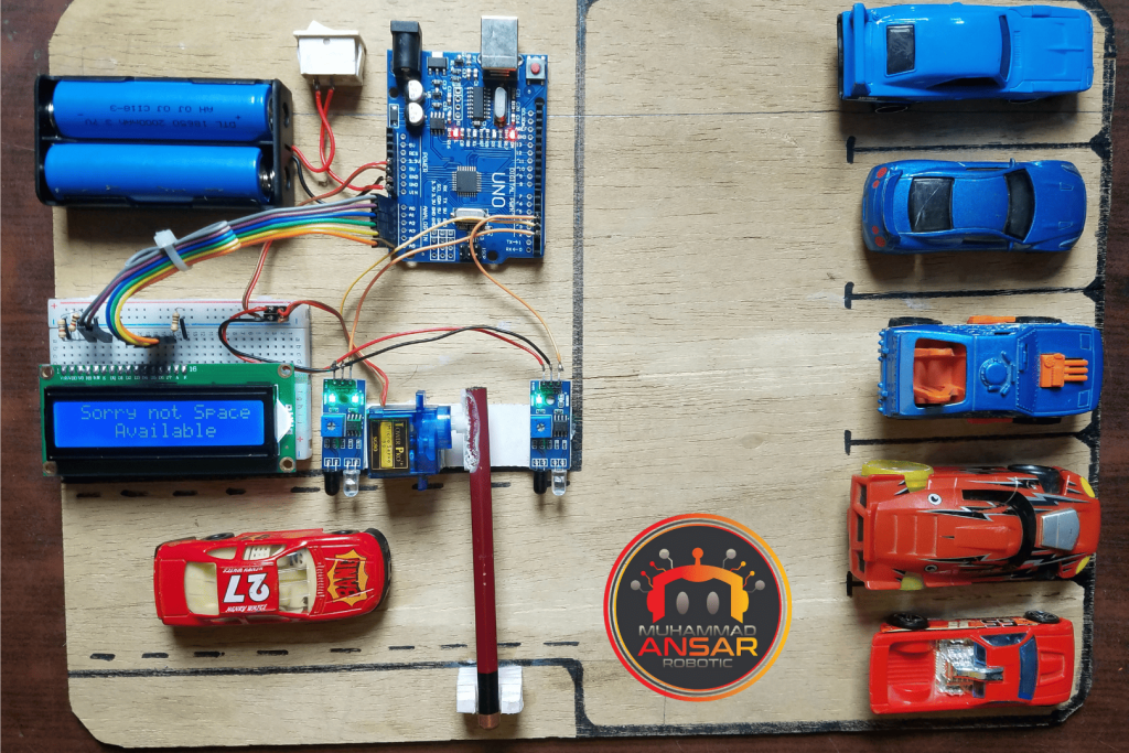
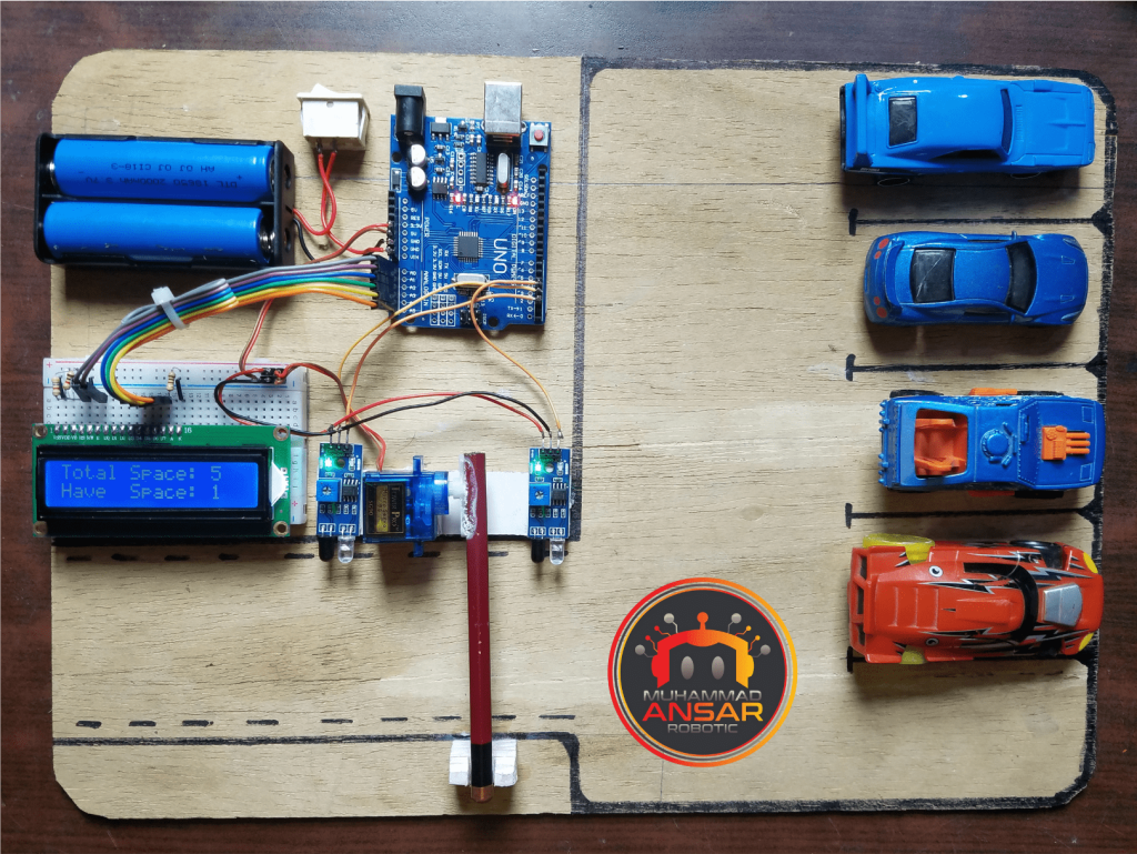
It’s time to test your car parking system when you’ve completed building the circuit and uploading the code. Verify that every part is functioning as it should. It should be visible that the servo motor is correcting the alignment and the IR sensors are sensing the location of the automobile.
Conclusion
In conclusion, building an Arduino and IR sensor car parking system is a useful and enjoyable project. It not only assists with precise parking but also serves as an example of how technology can make daily jobs easier.
4 responses to “Car Parking System Using Arduino And IR Sensor”

I used Atmega8 instead of Arduino, please help me to write its source code. I am a beginner and high school student.
LCD pin ProtB , IR sensor PD0,PD2 , Servo PD1 , Alarm LED PD3.Very nice project, thank you
welcome
I am absolutely assured of it.


4 thoughts on “Car Parking System Using Arduino And IR Sensor”
 Anna says:
I used Atmega8 instead of Arduino, please help me to write its source code. I am a beginner and high school student.
LCD pin ProtB , IR sensor PD0,PD2 , Servo PD1 , Alarm LED PD3.- Ahmed Al Shawafi says:
Very nice project, thank you
Leave a Reply