
Line Follower Obstacle Avoiding Controlled By IR Remote And Mobile
Introduction
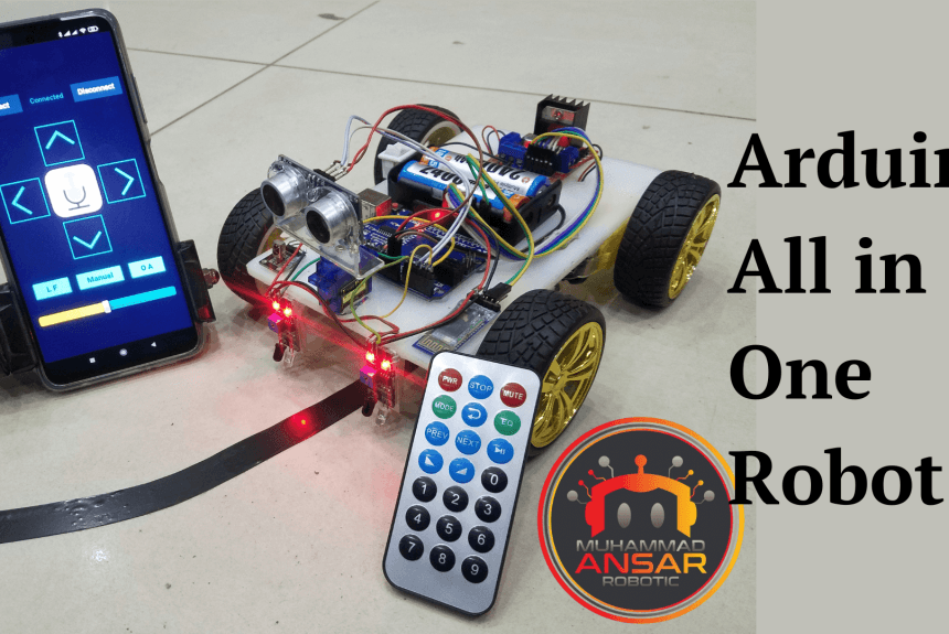
Are you prepared to take a thrilling trip into the realm of robotics? We’ll expose you to the intriguing Arduino All-in-One Robot project in this blog article. This adaptable robot can be operated with an IR remote or even your smartphone, and it can follow lines and avoid obstructions, among other things. You will be able to construct your own multipurpose robot with a list of necessary parts and a little bit of programming wizardry.
MArobotics proposes a multipurpose robotics project called the “Line Follower Obstacle Avoiding System Controlled by IR Remote and Mobile.” This unique technology combines line-following capabilities with obstacle avoidance to provide a complete solution for autonomous navigation. The project, which can be controlled via an IR remote as well as a mobile device, demonstrates user interaction variety. The combination of these features makes it appropriate for a wide range of applications, from instructional robotics to autonomous guided vehicles. The MArobotics project highlights an advanced and interactive approach to robotics, providing a dynamic platform for learning and experimentation in the field of autonomous systems. So let’s examine how to make this great idea come to life by delving into the world of DIY robots.
Components Required
- 5mm Acrylic Sheet 20cm x 12cm
- DC Gear Motor x 4
- Arduino UNO
- IR Sensor x 2
- L298 Motor Driver
- HC-05 Bluetooth Module
- IR Receiver Module
- MP3 Player IR Remote
- SG90 Servo Motor
- Ultrasonic Sensor Holder
- Ultrasonic Sensor HC-SR04
- 4Pcs Smart Robot Car Tyers Wheels
- Male to Female Jumper Wires
- On/Off Switch
- 18650 Battery Holder – 2 Cell
- 18650 Battery Cell 3.7V x 2
Circuit Diagram
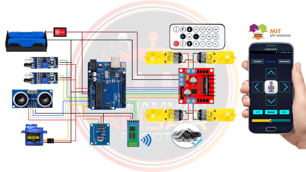
It all begins with a power supply that is made up of two series-connected 3.7-volt batteries that provide 7.4 volts in total. We’ve included a convenient on/off switch to regulate the power flow.
The Arduino UNO, which acts as the microcontroller and orchestrates all the movements, is the brains of our robot. We have included two infrared sensors for obstacle avoidance and line following so the robot can sense its environment. We’ve added an HC-SR04 ultrasonic sensor for measuring distance. We’ve used an HC-05 Bluetooth module for mobile control, an IR receiver for remote commands, and a tiny servo motor for directional control to increase the mobility of our robot. An L298 motor driver with outputs set aside for the left and right side motors is supplied to control the motors. We’ve included an infrared remote for MP3 operations for your convenience. The remote’s buttons have different functions: “>” stops the robot, “+” advances it, “-” reverses its direction, “>>|” turns it right, and “|<<” turns it left. Additionally, we’ve added the buttons “1, 2,” and “3” to start the obstacle avoidance, line follower, and manual functions, respectively. We used MIT App Inventor to create an Android application that will provide mobile control. Connecting and disconnecting, directing the robot’s movement in all directions, speech recognition, line following, manual control, and obstacle avoidance are all accomplished via the app’s buttons. The user may also change the robot’s speed with a slider. Now that you have the circuit schematic and hardware assembled, you can activate your Arduino All-in-One Robot and enable it to carry out a variety of fascinating tasks, such as autonomous navigation and reacting to remote and mobile orders.
Arduino IDE Code
#include <SoftwareSerial.h>
SoftwareSerial BT_Serial(2, 3); // RX, TX
#include <IRremote.h>
const int RECV_PIN = A5;
IRrecv irrecv(RECV_PIN);
decode_results results;
#define enA 10//Enable1 L298 Pin enA
#define in1 9 //Motor1  L298 Pin in1
#define in2 8 //Motor1  L298 Pin in1
#define in3 7 //Motor2  L298 Pin in1
#define in4 6 //Motor2  L298 Pin in1
#define enB 5 //Enable2 L298 Pin enB
#define servo A4
#define R_S A0 //ir sensor Right
#define L_S A1 //ir sensor Left
#define echo A2    //Echo pin
#define trigger A3 //Trigger pin
int distance_L, distance_F = 30, distance_R;
long distance;
int set = 20;
int bt_ir_data; // variable to receive data from the serial port and IRremote
int Speed = 130;
int mode=0;
int IR_data;
void setup(){ // put your setup code here, to run once
pinMode(R_S, INPUT); // declare if sensor as input
pinMode(L_S, INPUT); // declare ir sensor as input
pinMode(echo, INPUT );// declare ultrasonic sensor Echo pin as input
pinMode(trigger, OUTPUT); // declare ultrasonic sensor Trigger pin as Output
pinMode(enA, OUTPUT); // declare as output for L298 Pin enA
pinMode(in1, OUTPUT); // declare as output for L298 Pin in1
pinMode(in2, OUTPUT); // declare as output for L298 Pin in2
pinMode(in3, OUTPUT); // declare as output for L298 Pin in3
pinMode(in4, OUTPUT); // declare as output for L298 Pin in4
pinMode(enB, OUTPUT); // declare as output for L298 Pin enB
irrecv.enableIRIn(); // Start the receiver
irrecv.blink13(true);
Serial.begin(9600); // start serial communication at 9600bps
BT_Serial.begin(9600);
pinMode(servo, OUTPUT);
 for (int angle = 70; angle <= 140; angle += 5)  {
   servoPulse(servo, angle);  }
 for (int angle = 140; angle >= 0; angle -= 5)  {
   servoPulse(servo, angle);  }
 for (int angle = 0; angle <= 70; angle += 5)  {
   servoPulse(servo, angle);  }
delay(500);
}
void loop(){
if(BT_Serial.available() > 0){  //if some date is sent, reads it and saves in state
bt_ir_data = BT_Serial.read();
Serial.println(bt_ir_data);
if(bt_ir_data > 20){Speed = bt_ir_data;}
}
if (irrecv.decode(&results)) {
Serial.println(results.value,HEX);
bt_ir_data = IRremote_data();
Serial.println(bt_ir_data);
irrecv.resume(); // Receive the next value
delay(100);
}
     if(bt_ir_data == 8){mode=0; Stop();}    //Manual Android Application and IR Remote Control Command
else if(bt_ir_data == 9){mode=1; Speed=130;} //Auto Line Follower Command
else if(bt_ir_data ==10){mode=2; Speed=255;} //Auto Obstacle Avoiding Command
analogWrite(enA, Speed); // Write The Duty Cycle 0 to 255 Enable Pin A for Motor1 Speed
analogWrite(enB, Speed); // Write The Duty Cycle 0 to 255 Enable Pin B for Motor2 Speed
if(mode==0){
//===============================================================================
//                          Key Control Command
//===============================================================================
     if(bt_ir_data == 1){forword(); }  // if the bt_data is '1' the DC motor will go forward
else if(bt_ir_data == 2){backword();}  // if the bt_data is '2' the motor will Reverse
else if(bt_ir_data == 3){turnLeft();}  // if the bt_data is '3' the motor will turn left
else if(bt_ir_data == 4){turnRight();} // if the bt_data is '4' the motor will turn right
else if(bt_ir_data == 5){Stop(); }     // if the bt_data '5' the motor will Stop
//===============================================================================
//                          Voice Control Command
//===============================================================================
else if(bt_ir_data == 6){turnLeft();  delay(400);  bt_ir_data = 5;}
else if(bt_ir_data == 7){turnRight(); delay(400);  bt_ir_data = 5;}
}
if(mode==1){
//===============================================================================
//                          Line Follower Control
//===============================================================================
if((digitalRead(R_S) == 0)&&(digitalRead(L_S) == 0)){forword();}  //if Right Sensor and Left Sensor are at White color then it will call forword function
if((digitalRead(R_S) == 1)&&(digitalRead(L_S) == 0)){turnRight();}//if Right Sensor is Black and Left Sensor is White then it will call turn Right function
if((digitalRead(R_S) == 0)&&(digitalRead(L_S) == 1)){turnLeft();} //if Right Sensor is White and Left Sensor is Black then it will call turn Left function
if((digitalRead(R_S) == 1)&&(digitalRead(L_S) == 1)){Stop();}     //if Right Sensor and Left Sensor are at Black color then it will call Stop function
}
if(mode==2){
//===============================================================================
//                          Obstacle Avoiding Control
//===============================================================================
 distance_F = Ultrasonic_read();
 Serial.print("S=");Serial.println(distance_F);
  if (distance_F > set){forword();}
    else{Check_side();}
}
delay(10);
}
long IRremote_data(){
     if(results.value==0xFF02FD){IR_data=1;}
else if(results.value==0xFF9867){IR_data=2;}
else if(results.value==0xFFE01F){IR_data=3;}
else if(results.value==0xFF906F){IR_data=4;}
else if(results.value==0xFF629D || results.value==0xFFA857){IR_data=5;}
else if(results.value==0xFF30CF){IR_data=8;}
else if(results.value==0xFF18E7){IR_data=9;}
else if(results.value==0xFF7A85){IR_data=10;}
return IR_data;
}
void servoPulse (int pin, int angle){
int pwm = (angle*11) + 500;      // Convert angle to microseconds
 digitalWrite(pin, HIGH);
 delayMicroseconds(pwm);
 digitalWrite(pin, LOW);
 delay(50);                   // Refresh cycle of servo
}
//**********************Ultrasonic_read****************************
long Ultrasonic_read(){
  digitalWrite(trigger, LOW);
  delayMicroseconds(2);
  digitalWrite(trigger, HIGH);
  delayMicroseconds(10);
  distance = pulseIn (echo, HIGH);
  return distance / 29 / 2;
}
void compareDistance(){
       if (distance_L > distance_R){
  turnLeft();
  delay(350);
  }
  else if (distance_R > distance_L){
  turnRight();
  delay(350);
  }
  else{
  backword();
  delay(300);
  turnRight();
  delay(600);
  }
}
void Check_side(){
    Stop();
    delay(100);
 for (int angle = 70; angle <= 140; angle += 5)  {
   servoPulse(servo, angle);  }
    delay(300);
    distance_L = Ultrasonic_read();
    delay(100);
  for (int angle = 140; angle >= 0; angle -= 5)  {
   servoPulse(servo, angle);  }
    delay(500);
    distance_R = Ultrasonic_read();
    delay(100);
 for (int angle = 0; angle <= 70; angle += 5)  {
   servoPulse(servo, angle);  }
    delay(300);
    compareDistance();
}
void forword(){  //forword
digitalWrite(in1, HIGH); //Right Motor forword Pin
digitalWrite(in2, LOW);  //Right Motor backword Pin
digitalWrite(in3, LOW);  //Left Motor backword Pin
digitalWrite(in4, HIGH); //Left Motor forword Pin
}
void backword(){ //backword
digitalWrite(in1, LOW);  //Right Motor forword Pin
digitalWrite(in2, HIGH); //Right Motor backword Pin
digitalWrite(in3, HIGH); //Left Motor backword Pin
digitalWrite(in4, LOW);  //Left Motor forword Pin
}
void turnRight(){ //turnRight
digitalWrite(in1, LOW);  //Right Motor forword Pin
digitalWrite(in2, HIGH); //Right Motor backword Pin
digitalWrite(in3, LOW);  //Left Motor backword Pin
digitalWrite(in4, HIGH); //Left Motor forword Pin
}
void turnLeft(){ //turnLeft
digitalWrite(in1, HIGH); //Right Motor forword Pin
digitalWrite(in2, LOW);  //Right Motor backword Pin
digitalWrite(in3, HIGH); //Left Motor backword Pin
digitalWrite(in4, LOW);  //Left Motor forword Pin
}
void Stop(){ //stop
digitalWrite(in1, LOW); //Right Motor forword Pin
digitalWrite(in2, LOW); //Right Motor backword Pin
digitalWrite(in3, LOW); //Left Motor backword Pin
digitalWrite(in4, LOW); //Left Motor forword Pin
}MIT APP Inventor
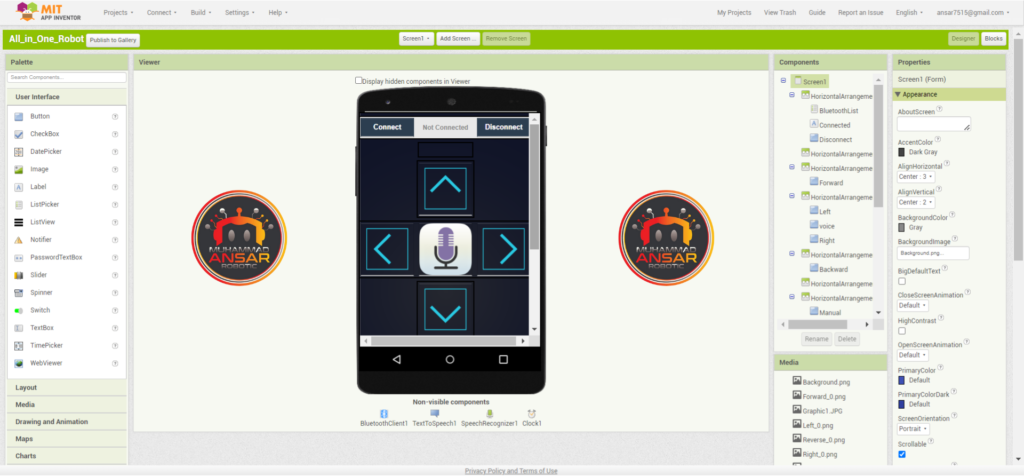
Make sure the “IRremote” library is installed to your Arduino IDE before beginning our Arduino All in One Robot project. If this library is not installed, compiling the code can result in issues. The library may be accessed by going to the “Tools” menu. After organizing the library, choose the relevant board—in this example, the “Arduino UNO”—from the “Tools” menu. Next, choose the appropriate port to connect your Arduino board to the computer. The code is now ready to be uploaded to your board. Your robot is now ready to operate after the code has been successfully uploaded, but don’t overlook the importance of the Android application made with MIT App Inventor. You have a “aia” file and a “apk” file in the project files. Install the “apk” file on your Android smartphone to begin using the app. You may upload the “aia” file to the MIT App Inventor website in order to modify or customize the app. Through this method, you may adjust the style and functionality of the app to suit your tastes. An easy-to-use interface is offered by the MIT App Inventor to enable these modifications. Visit the MIT App Inventor website and sign in with your Gmail account to upload the “aia” file. Create a new project, give it a name, and choose the buttons and components you want. Next, pick the “aia” file you previously downloaded by going to the “Projects” area and using the “Import project.aia from my computer” option. You may alter the app’s graphical components, like as buttons, backgrounds, and colors, after uploading.
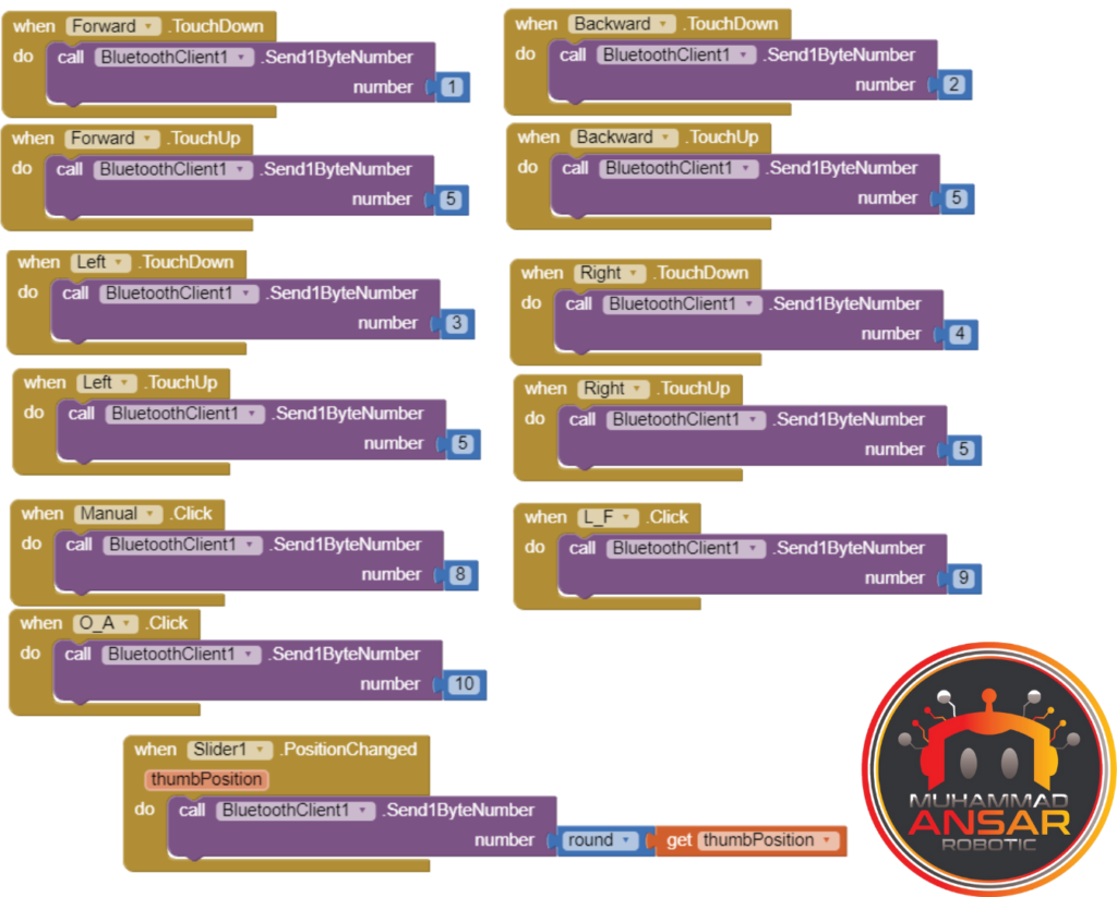
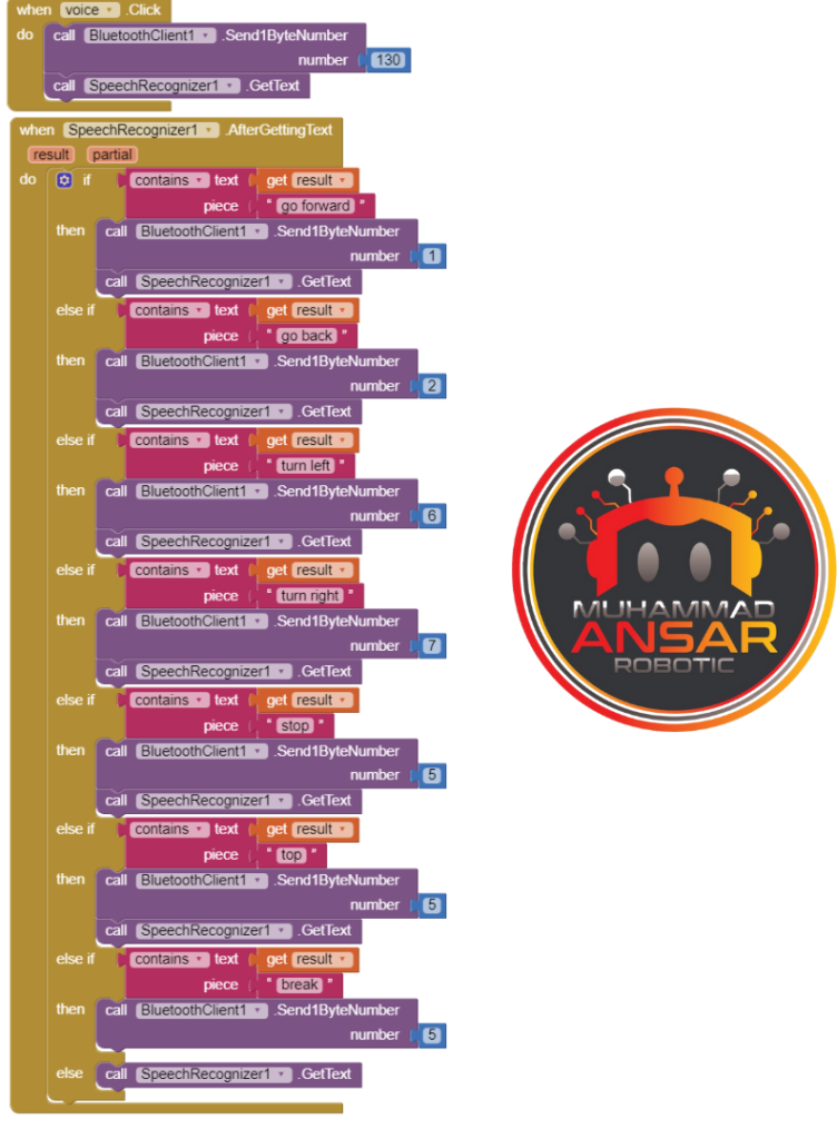
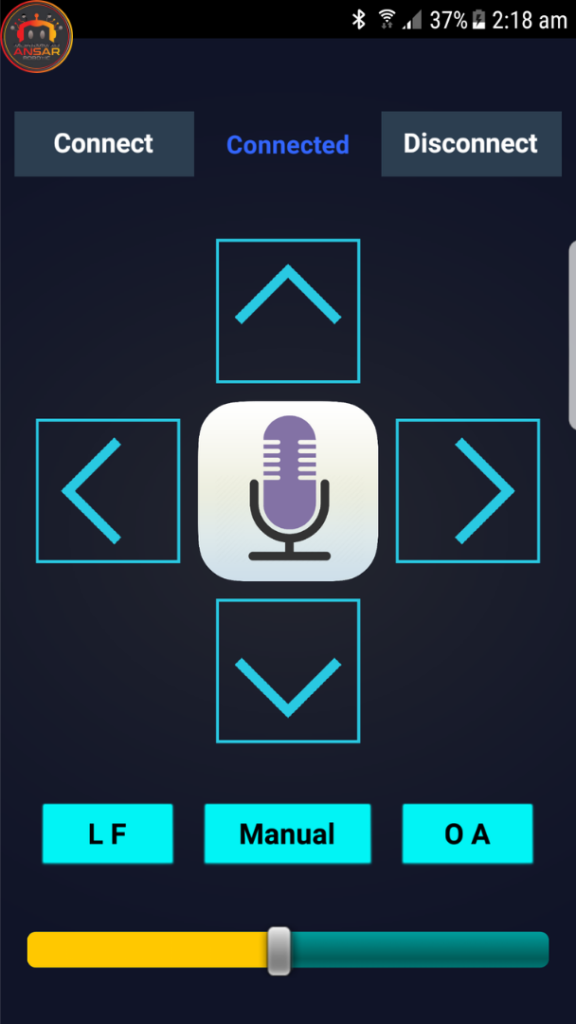
The functionality of the app is to enable Bluetooth connection between you and your robot. When you click the “Connect” button, a selection of compatible Bluetooth devices appears. By choosing the HC-05 device, you may link your smartphone to the robot. The software has buttons on it that may be used to move the robot left, right, forward, and backward. The software has voice recognition built into it as well, so you can operate the robot with spoken commands. Furthermore, you may choose between certain features like obstacle avoidance, manual control, and line following. There is a slider to set the duty cycle and change the robot’s pace. To guarantee that the robot understands and carries out your orders precisely, the software translates spoken commands into appropriate numeric codes. The reasoning for the app’s functioning is contained in the “blocks” part of the code. It decodes your movements and converts them into instructions for the robot. This is where movements such as forward, backward, left or right turns, and stops are defined.
You may construct the “apk” file from the MIT App Inventor website, download it, and install it on your Android smartphone when you’ve finished customizing the app and testing it on your phone. Your robot now has a smart mobile interface for control and interaction in addition to its physical capabilities.
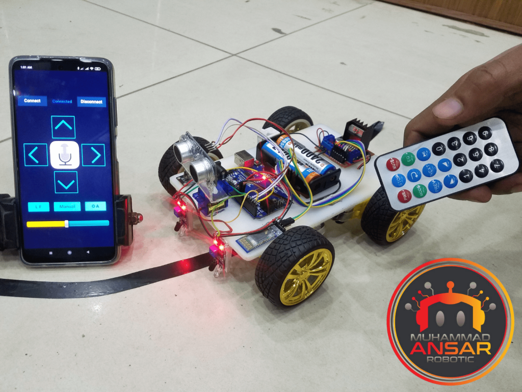
Hardware Testing
First, make sure that the power is on before delving into the robot’s functioning. Two 3.7-volt batteries linked in series provide a total of 7.4 volts as the robot’s power source. The IR sensors must be calibrated when the electricity is established. They may not react at first to surfaces that transition from black to white. To ensure that the sensors react appropriately when they detect changes between black and white surfaces, you may calibrate them by rotating the sensors in either an anticlockwise or clockwise orientation. An IR remote for controlling MP3 players is incorporated into the project as part of the hardware configuration. There are many buttons on this remote for different purposes. For example, the robot can move ahead by pressing the advance button, and it can stop moving by pressing the stop buttons. The robot can turn in the directions indicated by the right and left buttons, and it can walk backward by pressing the back button. Furthermore, the robot’s obstacle avoidance, line following, and manual control capabilities are initiated by pressing the “1,” “2,” and “3” buttons.
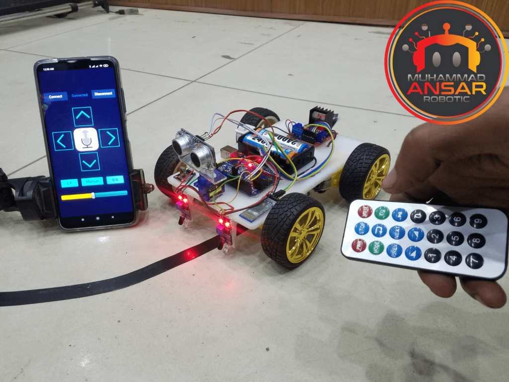
It’s time to take out the IR remote and give the robot a go to see how it works. The robot can go ahead by pushing the forward button, and it can stop by hitting the stop button. In a similar vein, the robot moves backward and stops when the reverse and stop buttons are pressed simultaneously. The robot may rotate in the directions indicated by the right and left buttons, and it can stop moving altogether using the stop button. It’s now time to switch on to the voice control feature after this preliminary test. The robot may be controlled using vocal instructions such as “Go Forward,” “Stop,” “Go Back,” “Turn Right,” “Turn Left,” and “Break.” When you give vocal orders, the robot interprets them into appropriate numeric codes so that your directions are carried out precisely. After you’ve experimented with the voice control functions, it’s time to switch the mode of the robot to line following. When the robot presses button “2” on the IR remote, it begins to follow a line, showcasing its automatic navigational capabilities. You may put the robot in obstacle avoidance mode when the line following test is successful. In this phase, the robot gains the ability to recognize and avoid obstacles in its path. The demonstration of manual control with an IR remote concludes. Once the robot is in manual control mode, you may control its direction by pushing buttons on the IR remote control, including turning it left, right, forward, backward, and stopping it. The robot’s motions can be easily controlled with the help of these controllers.
Conclusion
To sum up, the Arduino All-in-One Robot project is proof of the limitless potential of innovation and technology. You’ve built a flexible robot that can follow lines, explore its environment, and react to remote orders by assembling a variety of parts and learning to code. Irrespective of your level of expertise with robotics, this project you an excellent chance to enhance your skills and create something absolutely amazing.
5 responses to “Line Follower Obstacle Avoiding Controlled By IR Remote And Mobile”

hello please I want the circuit diagram without the watermark
bro we can avoid mp3 remote
Bhai apk app ki link
Bhai mere aurdino ko 12 v supply de raha hu vin pin se tu uska regulatar ic phok ja raha he


5 thoughts on “Line Follower Obstacle Avoiding Controlled By IR Remote And Mobile”
 omar_hossam_zayed says:
hello please I want the circuit diagram without the watermark
- maqsud says:
bro we can avoid mp3 remote
- Pawan says:
Bhai apk app ki link
- Pawan says:
Bhai mere aurdino ko 12 v supply de raha hu vin pin se tu uska regulatar ic phok ja raha he
Leave a Reply