
Arduino Based Home Automation Controlled by Android
Introduction
The ability to operate household appliances with a single button push is no longer a pipe dream in the age of automation. You can build a home automation system that lets you operate fans and lights from your smartphone by utilizing the strength of Arduino and the ease of use of your Android smartphone. We’ll walk you through the steps of constructing a do-it-yourself home appliance control system with Arduino and a specific Android app in this blog article.
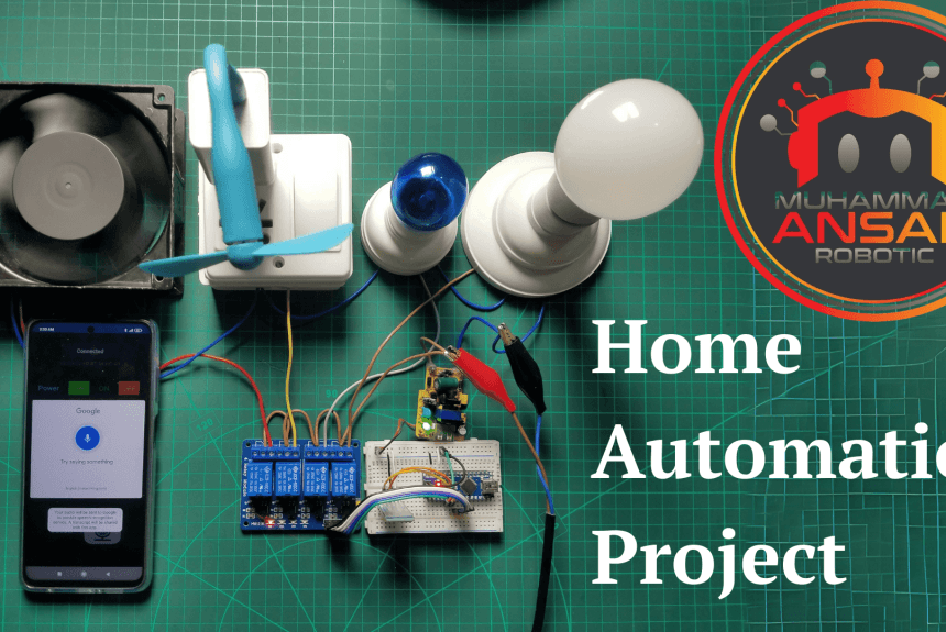
MArobotics develops a sophisticated “Arduino Based Home Automation” solution that can be operated easily from Android devices. This ingenious initiative allows users to control a variety of home appliances, including light bulbs, tiny lights, plugs with fans, and fans, using a specific Android app. The automation system includes not only manual control buttons, but also voice control functions, for added convenience. MArobotics’ project is a user-friendly and adaptable solution that combines Arduino and Android technology to provide a full home automation experience that is compatible with current smart living.
Components Required
- Solderless Breadboard
- Arduino Nano
- HC-05 Bluetooth Module
- 4-Channel 5V Relay Module
- Male to Female Jumper Wires
- Male to Male Jumper Wires
- Bulb Holder x 2
- 220V LED Bulb x 2
- AC Fan 220V
- 5V 2Amp Power Adapter
Circuit Diagram
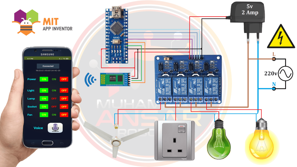
The Arduino Nano, which functions as the system’s brain, is at its center. The HC-05 Bluetooth module is then included, creating a wireless communication link between the Arduino and the Android application. The circuit incorporates a 4-channel relay module for controlling numerous appliances. The load is immediately linked to the neutral when the power source, which supplies 220 volts, is put into the system. The usually open output of the relay is connected to the load, and the line from the power supply is connected to the relay’s common terminal. A 5-volt, 2-ampere power adapter powers the whole arrangement, providing a steady source of power for the Arduino Nano, Bluetooth module, and relay module. The MIT App Inventor website was utilized to create the Android app, which serves as the linked appliances’ user interface. After gaining an understanding of the circuit layout, the next step is to physically connect the hardware parts according to this schematic in order to activate the system. This thorough integration creates a unified home automation system by enabling smooth communication between the Arduino, Bluetooth module, and Android application.
Arduino IDE Code
#include <EEPROM.h>
#include <SoftwareSerial.h>
SoftwareSerial BT_Serial(2, 3); // RX, TX

#define Relay1 4 // Load1 Pin Out
#define Relay2 5 // Load2 Pin Out
#define Relay3 6 // Load3 Pin Out
#define Relay4 7 // Load4 Pin Out

char bt_data; // variable to receive data from the serial port
int load1, load2, load3, load4, power;

void setup(){
Serial.begin(9600);
BT_Serial.begin(9600);

pinMode(Relay1, OUTPUT); digitalWrite(Relay1, 1);
pinMode(Relay2, OUTPUT); digitalWrite(Relay2, 1);
pinMode(Relay3, OUTPUT); digitalWrite(Relay3, 1);
pinMode(Relay4, OUTPUT); digitalWrite(Relay4, 1);

load1 = EEPROM.read(1);
load2 = EEPROM.read(2);
load3 = EEPROM.read(3);
load4 = EEPROM.read(4);

power = EEPROM.read(5);
delay(500);
}

void loop() {
if(BT_Serial.available()>0){bt_data = BT_Serial.read();}

if(bt_data == 'A'){load1=0;EEPROM.write(1, load1);}
if(bt_data == 'a'){load1=1;EEPROM.write(1, load1);}

if(bt_data == 'B'){load2=0;EEPROM.write(2, load2);}
if(bt_data == 'b'){load2=1;EEPROM.write(2, load2);}

if(bt_data == 'C'){load3=0;EEPROM.write(3, load3);}
if(bt_data == 'c'){load3=1;EEPROM.write(3, load3);}

if(bt_data == 'D'){load4=0;EEPROM.write(4, load4);}
if(bt_data == 'd'){load4=1;EEPROM.write(4, load4);}

if(bt_data == 'E'){power=0;EEPROM.write(5, power);}
if(bt_data == 'e'){power=1;EEPROM.write(5, power);}

bt_data = '0';

if(power==1){
digitalWrite(Relay1, 1);
digitalWrite(Relay2, 1);
digitalWrite(Relay3, 1);
digitalWrite(Relay4, 1);
}else{
digitalWrite(Relay1, load1);
digitalWrite(Relay2, load2);
digitalWrite(Relay3, load3);
digitalWrite(Relay4, load4);
}

 BT_Serial.print(power); //send distance to MIT App
 BT_Serial.print(";");
 BT_Serial.print(load1); //send distance to MIT App
 BT_Serial.print(";");
 BT_Serial.print(load2); //send distance to MIT App
 BT_Serial.print(";");
 BT_Serial.print(load3); //send distance to MIT App
 BT_Serial.print(";");
 BT_Serial.print(load4); //send distance to MIT App
 BT_Serial.println(";");

delay(500);
}
Explanation
To maintain the load’s status, the EEPROM library is first incorporated into the Arduino code that is given. The configuration of the system is maintained even after a power cycle thanks to the EEPROM, which is used to save the status of each load. In addition, the Bluetooth module (HC-05) does not need to be detached during code upload since the SoftwareSerial library is used to create a custom serial (BT_Serial). Initialization is done for the Bluetooth data and load status variables, as well as the pin configurations for the 4-channel relay module. The setup step sets the relay pin configuration, baud rates for the built-in serial and Bluetooth serial, and starting states for the loads depending on EEPROM data.
In the loop section that follows, the code reads data from the Bluetooth serial continually. Corresponding actions are performed based on the received data (A, B, C, D, or E, reflecting various loads and the power). For example, ‘A’ indicates a request to activate Load 1 (a light, for example), change its variable to 0 and update the EEPROM appropriately. On the other hand, ‘a’ denotes a request to set its variable to 1 and disable Load 1. The power state (E) and the other loads (B, C, D) follow a similar logic, offering a complete control system.
With the help of Bluetooth instructions, the code updates load statuses and power circumstances in a methodical manner, guaranteeing synchronization between the Arduino and the Android application. Real time updates on the Android app are made possible by the code, which prints the current power and load status. Furthermore, a 500 millisecond delay is included to ensure that the loop runs smoothly. The software component for the home appliance control system is then fully integrated when the code is uploaded to the Arduino Nano using the Arduino IDE.
MIT APP Inventor
The MIT App Inventor was used to create the companion Android application for the home appliance control system. This tool offered an easy-to-use interface for designing graphical user interfaces without requiring a deep understanding of programming. To start the process, go to the MIT App Inventor website, sign in using your Gmail account, and start a new project. After that, the graphical user interface (GUI) for the app was built, with buttons to regulate different loads, a button to link Bluetooth, and labels to show the current state of each load and power.
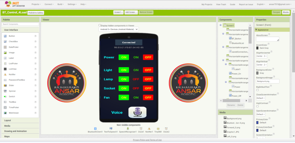
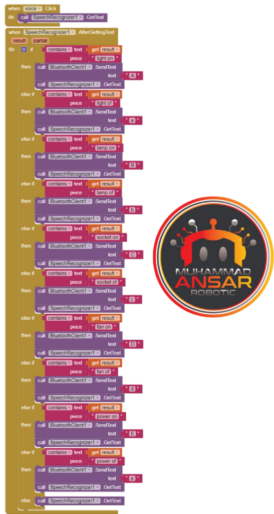
The application’s auto-connection functionality streamlines the user experience by emphasizing that it instantly connects to the previously associated Bluetooth module when it is opened. In addition, the application’s general functioning depends on the graphic components, including buttons and labels. The voice control element of the app was described, showing how speech recognition was used to translate spoken instructions into text, before moving on to the functionalities of the app. This innovation improved the accessibility and hands-free operation of the home automation system by enabling users to regulate the loads and power using voice commands.
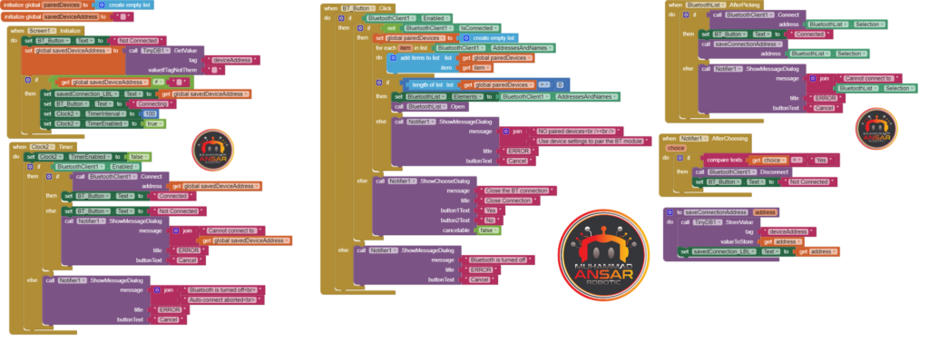
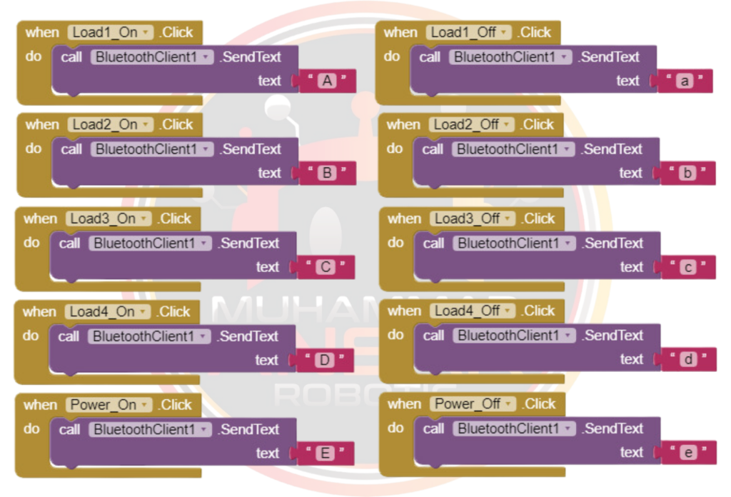
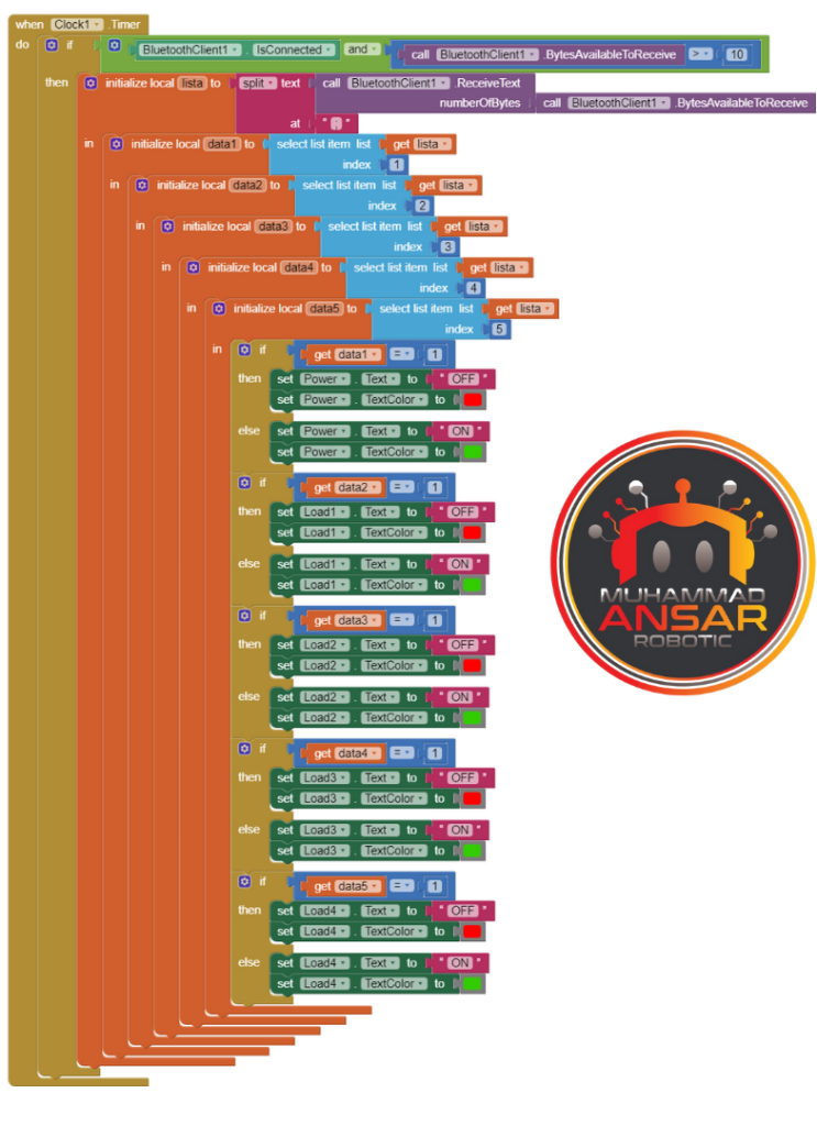
The MIT App Inventor’s blocks component, which depicts the app’s visual programming logic, was demonstrated. Each block was well explained, showing how it worked with the Bluetooth module and converted user inputs into commands for the Arduino. Users received real-time feedback on the application’s interface through the explanation of the color-coded text updates based on the power and load condition. Users were guided through the steps to download and install the APK file from MIT App Inventor on an Android device by outlining the process of producing the APK file. In order to connect the Bluetooth module to the Arduino-based home appliance control system, the last step was to pair it with the app. All things considered, the combination of the Arduino hardware with the MIT App Inventor provided a complete home automation solution, enabling consumers to simply operate their appliances using both voice and physical controls.
Hardware Testing
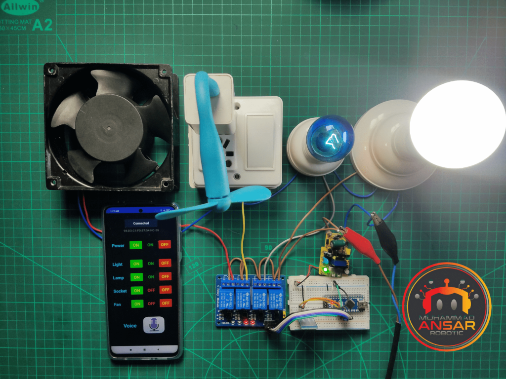
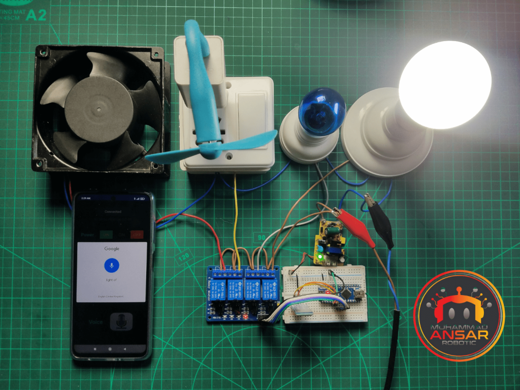
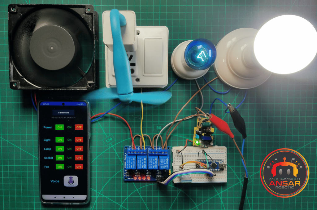
After connecting the hardware and installing the Android app, connect it to Bluetooth. On app there re two ways to control the appliances. One way is to control using manual buttons and other way is to control using voice commands.
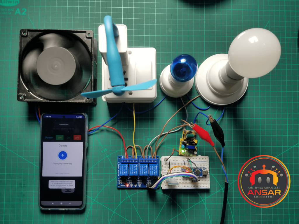
For example, if you will choose voice command button and say “Light ON”, it will turn on the light.
Conclusion
In addition to making your life more convenient, home automation helps you conserve energy and lessen your carbon impact. Anyone interested in IoT applications and DIY electronics should start with this project. Your house may become a smart, automated sanctuary by adding more features and expanding the system to manage more appliances with a little imagination and resourcefulness.
3 responses to “Arduino Based Home Automation Controlled by Android”

Sushant Gautam
Is it possible for you to share the mit apk app
220 volt ke liye konsi relay best hai


Related Posts

IOT And Manual Switch Control Home Appliances Using Firebase Server
3 thoughts on “Arduino Based Home Automation Controlled by Android”
 Mbugua says:
Is it possible for you to share the mit apk app
- mohd ali jamal says:
220 volt ke liye konsi relay best hai
Leave a Reply