
Arduino Based Black Line Follower Robot

Introduction
An interesting project that incorporates robotics, electronics, and programming is building a line follower robot. We’ll walk you through the process of creating your very own black line follower robot on an Arduino platform in this blog article. This project is a fantastic chance to practice your programming abilities in a real-world scenario, in addition to learning a lot about robotics. Now let’s dig in and discover the intriguing realm of robots that follow lines!
Components Required
- 5mm Acrylic Sheet (20cm x 12cm)
- DC Gear Motor x 4
- Arduino UNO
- IR Sensor x 2
- L298 Motor Driver
- 4Pcs Smart Robot Car Tyers Wheels
- Male to Female Jumper Wires
- On/Off Switch
- 18650 Battery Holder – 2 Cell
- 18650 Battery Cell 3.7V x 2
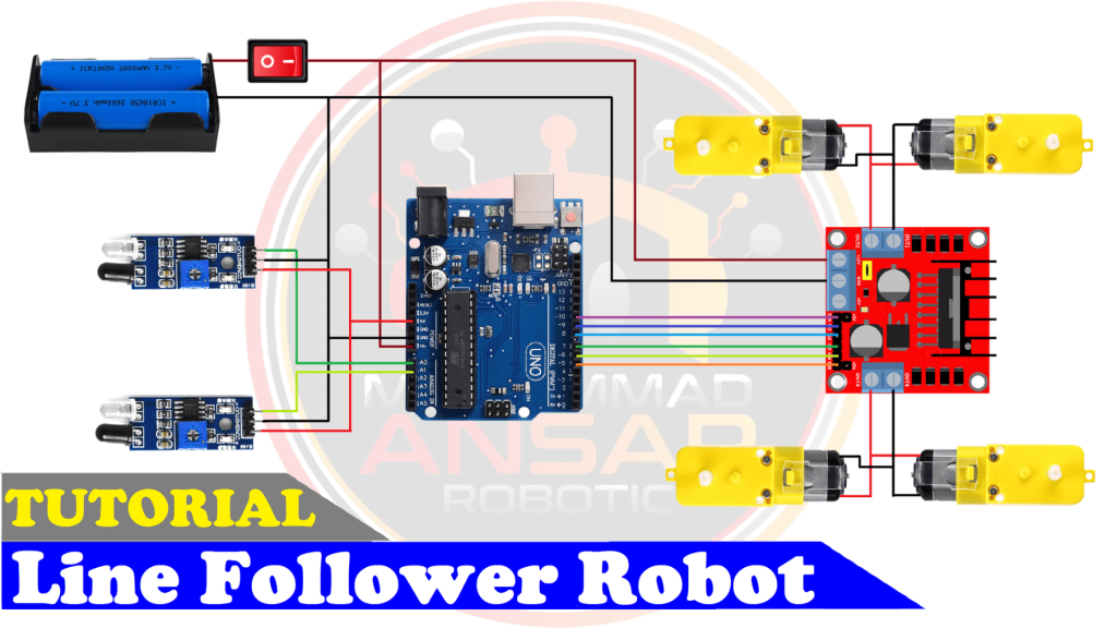
Circuit Diagram
Knowing how the parts fit together is crucial before beginning the assembling process. A condensed circuit diagram that shows how each component works together is shown below. To guarantee correct operation, carefully follow this diagram. In this circuit diagram, an Arduino UNO is used as a microcontroller. A L293D motor driver is used that drives four dc motors. Two IR sensors are used to detect any obstacle on the way. Two cells of 3.7 volts are used as a power source. A power on/off switch is used. Output of the IR sensors are connected to A0 and A1 pin of the Arduino UNO.
Arduino IDE Code
#define enA 10//Enable1 L298 Pin enA
#define in1 9 //Motor1  L298 Pin in1
#define in2 8 //Motor1  L298 Pin in1
#define in3 7 //Motor2  L298 Pin in1
#define in4 6 //Motor2  L298 Pin in1
#define enB 5 //Enable2 L298 Pin enB

#define R_S A0 //ir sensor Right
#define L_S A1 //ir sensor Left

void setup(){ // put your setup code here, to run once

pinMode(R_S, INPUT); // declare if sensor as input
pinMode(L_S, INPUT); // declare ir sensor as input

pinMode(enA, OUTPUT); // declare as output for L298 Pin enA
pinMode(in1, OUTPUT); // declare as output for L298 Pin in1
pinMode(in2, OUTPUT); // declare as output for L298 Pin in2
pinMode(in3, OUTPUT); // declare as output for L298 Pin in3
pinMode(in4, OUTPUT); // declare as output for L298 Pin in4
pinMode(enB, OUTPUT); // declare as output for L298 Pin enB

analogWrite(enA, 150); // Write The Duty Cycle 0 to 255 Enable Pin A for Motor1 Speed
analogWrite(enB, 150); // Write The Duty Cycle 0 to 255 Enable Pin B for Motor2 Speed
delay(1000);
}
void loop(){
if((digitalRead(R_S) == 0)&&(digitalRead(L_S) == 0)){forword();}   //if Right Sensor and Left Sensor are at White color then it will call forword function

if((digitalRead(R_S) == 1)&&(digitalRead(L_S) == 0)){turnRight();} //if Right Sensor is Black and Left Sensor is White then it will call turn Right function

if((digitalRead(R_S) == 0)&&(digitalRead(L_S) == 1)){turnLeft();}  //if Right Sensor is White and Left Sensor is Black then it will call turn Left function

if((digitalRead(R_S) == 1)&&(digitalRead(L_S) == 1)){Stop();} //if Right Sensor and Left Sensor are at Black color then it will call Stop function
}

void forword(){  //forword
digitalWrite(in1, HIGH); //Right Motor forword Pin
digitalWrite(in2, LOW);  //Right Motor backword Pin
digitalWrite(in3, LOW);  //Left Motor backword Pin
digitalWrite(in4, HIGH); //Left Motor forword Pin
}

void turnRight(){ //turnRight
digitalWrite(in1, LOW);  //Right Motor forword Pin
digitalWrite(in2, HIGH); //Right Motor backword Pin
digitalWrite(in3, LOW);  //Left Motor backword Pin
digitalWrite(in4, HIGH); //Left Motor forword Pin
}

void turnLeft(){ //turnLeft
digitalWrite(in1, HIGH); //Right Motor forword Pin
digitalWrite(in2, LOW);  //Right Motor backword Pin
digitalWrite(in3, HIGH); //Left Motor backword Pin
digitalWrite(in4, LOW);  //Left Motor forword Pin
}

void Stop(){ //stop
digitalWrite(in1, LOW); //Right Motor forword Pin
digitalWrite(in2, LOW); //Right Motor backword Pin
digitalWrite(in3, LOW); //Left Motor backword Pin
digitalWrite(in4, LOW); //Left Motor forword Pin
}
Explanation
These lines define symbolic names for different pins and sensors using #define. In Arduino programming, this is a standard procedure to improve readability and maintainability of the code. To operate the motors, the digital pins linked to the L298 motor driver are named enA, in1, in2, in3, in4, and enB. The left and right infrared (IR) sensors are attached to analog pins denoted as L_S and R_S, respectively. The pinMode parameter in the setup() method determines whether the IR sensor pins are inputs or outputs. The motor speeds are set using analogWrite. The numbers go from 0 to 255, where 255 represents maximum speed and 0 represents off. To give the motors time to stabilize, a delay is inserted. The software uses digitalRead in the loop() method to determine the current statuses of the left (L_S) and right (R_S) infrared sensors. The robot’s movement is controlled by invoking the relevant function (forword(), turnRight(), turnLeft(), or Stop()) based on the sensor data. Based on the sensor data, these routines (forword(), turnRight(), turnLeft(), and Stop()) regulate the robot’s movement. They identify each motor’s orientation by applying the proper blends of high and low signals to the motor driver pins.
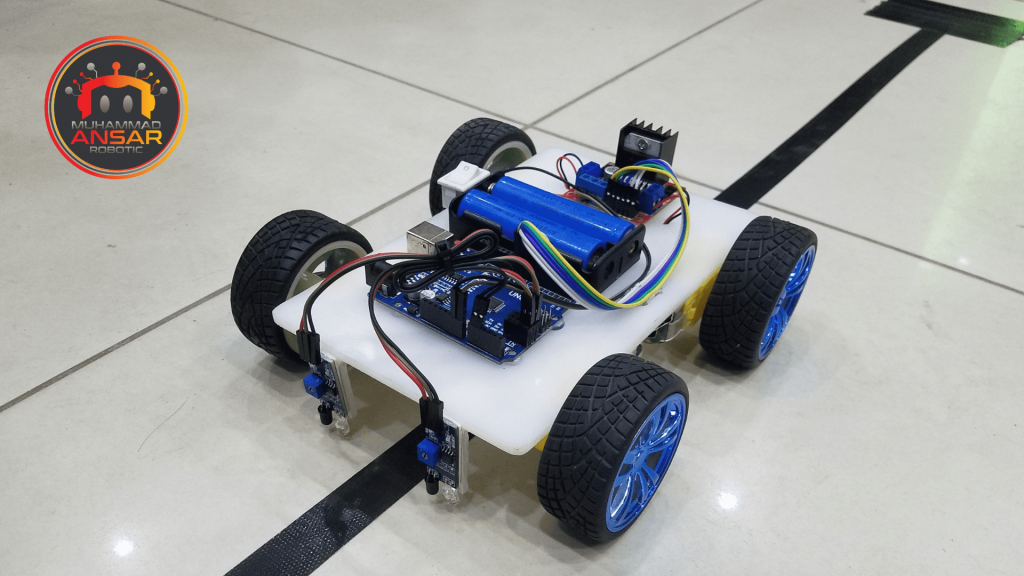
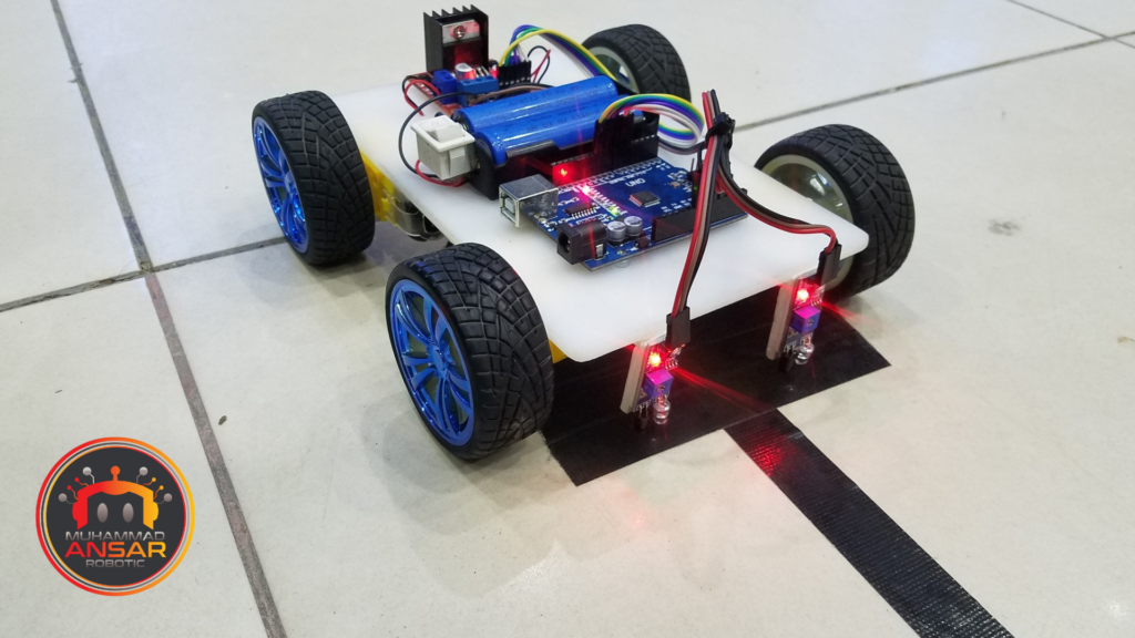
Hardware Testing
It’s time to test your line follower robot now that the circuit is put together and the programming has been uploaded. Turn it on, place it on a track with a black line, and watch it follow the course. You can modify the code or look for any faults in the circuit if necessary.
Conclusion
This project lays the groundwork for future, more difficult projects in addition to being an enjoyable and instructive method to learn about robotics and programming. Try with various line-following algorithms, improve the layout, and expose your robot to new tasks. There are countless options!
One response to “Arduino Based Black Line Follower Robot”

It’s working fine but not able to run faster has u show in this video , I am using same battery and it is not capable of pulling 4 motor. How can i solve the problem


Related Posts
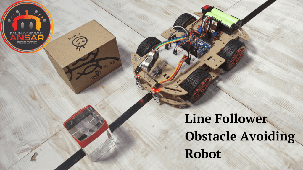
Line Follower Obstacle Avoiding Robot Using Arduino And L298 Motor Driver
One thought on “Arduino Based Black Line Follower Robot”
 Tharun P A says:
It’s working fine but not able to run faster has u show in this video , I am using same battery and it is not capable of pulling 4 motor. How can i solve the problem
Leave a Reply