
Digital Object Counter With Arduino

Introduction
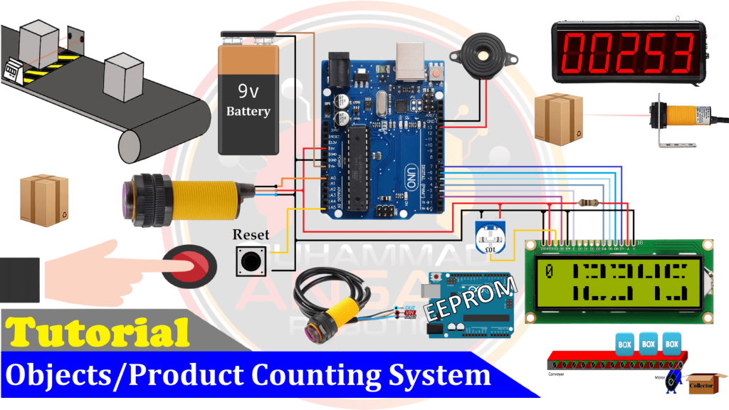
Arduino-powered digital item counters are a useful tool for tracking and recording the movement of goods in a variety of settings. With the help of this project, you may effectively automate the counting process for monitoring merchandise, people, or any other physical stuff. We’ll look at how to use Arduino to build a dependable object counting system in this blog article.
Components Required
- Solderless Breadboard
- Arduino UNO
- 16×2 LCD Display
- 100R Resistor
- E18-D80NK IR Sensor
- Push Button
- Buzzer
- Hard Jumper Wire
- Male to Male Jumper Wires
- Battery Clip
- 9V Battery
Proteus Simulation
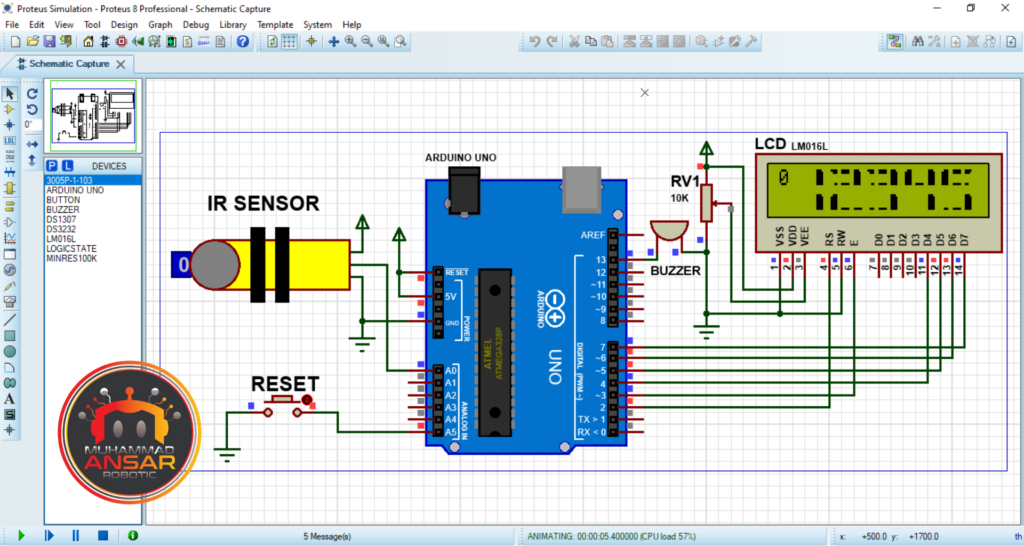
This simulation is made for Proteus 8.12 and shows how the parts of the Digital Object Counter are placed precisely. The setup consists of an Arduino, a 16×2 LCD screen with a 10k potentiometer for contrast control, an infrared sensor, a reset button, and a buzzer. The included Arduino IDE code generates a hex-file, which starts the simulation. The Arduino UNO board is chosen for compiling the code. The hex-file location is copied and put into the Arduino preferences after it has been built. An first message appears on the LCD after a 2000-millisecond delay when the simulation is running. After then, a 5-digit value is shown along with an update to the sensor’s status. The sensor state is toggled between 0 and 1, which causes the counting values to increase dynamically. The count is reset by holding down the reset button for three seconds. This simulation provides viewers with a full overview of the project and serves as a detailed explanation of the functioning of the Digital Object Counter.
Circuit Diagram
To guarantee clarity and simplicity of duplication, the circuit diagram for the Digital Object Counter project is provided in a methodical manner. The circuit starts with a 9V battery as the power supply and uses an Arduino UNO for central processing. A reset button is added to the circuit to enable the resetting feature after an IR sensor is installed in a strategic location. The project uses a 16×2 LCD for visual output, and a 10k potentiometer is linked to the contrast action pin to modify the LCD’s contrast. The LCD backlight pins (15 and 16) are set up as follows: pin 15 is the anode and pin 16 is the cathode. From the positive terminal, a 10-ohm resistance is connected in series to regulate the current flow to the anode. Finally, the circuit incorporates a buzzer. This thorough circuit schematic offers a clear manual for putting the hardware parts together in accordance with the functional specifications of the project.
Arduino IDE Code
#include <EEPROM.h>
#include <LiquidCrystal.h> //Libraries
LiquidCrystal lcd(2, 3, 4, 5, 6, 7); //Arduino pins to lcd

#define sensor_pin  A0
#define reset_pin   A5

#define buzzer 13

int d5=1, d4=2, d3=3, d2=4, d1=5;
int flag=0, timer=0;

// the 8 arrays that form each segment of the custom numbers
byte bar1[8]={B11100,B11110,B11110,B11110,B11110,B11110,B11110,B11100};
byte bar2[8]={B00111,B01111,B01111,B01111,B01111,B01111,B01111,B00111};
byte bar3[8]={B11111,B11111,B00000,B00000,B00000,B00000,B11111,B11111};
byte bar4[8]={B11110,B11100,B00000,B00000,B00000,B00000,B11000,B11100};
byte bar5[8]={B01111,B00111,B00000,B00000,B00000,B00000,B00011,B00111};
byte bar6[8]={B00000,B00000,B00000,B00000,B00000,B00000,B11111,B11111};
byte bar7[8]={B00000,B00000,B00000,B00000,B00000,B00000,B00111,B01111};
byte bar8[8]={B11111,B11111,B00000,B00000,B00000,B00000,B00000,B00000};

void setup(){ // put your setup code here, to run once

pinMode(sensor_pin, INPUT_PULLUP);
pinMode(reset_pin,  INPUT_PULLUP);

pinMode(buzzer, OUTPUT);

lcd.createChar(1,bar1);
lcd.createChar(2,bar2);
lcd.createChar(3,bar3);
lcd.createChar(4,bar4);
lcd.createChar(5,bar5);
lcd.createChar(6,bar6);
lcd.createChar(7,bar7);
lcd.createChar(8,bar8);

lcd.begin(16, 2); // Configura lcd numero columnas y filas
lcd.clear();
lcd.setCursor (0,0);
lcd.print("   Welcome To   ");
lcd.setCursor (0,1);
lcd.print(" Object Counter ");
delay(2000);
lcd.clear();


if(EEPROM.read(0)==0){
}else{
WriteEeprom();
EEPROM.write(0,0);
}

ReadEeprom();
}

void loop(){

if(digitalRead (sensor_pin) == 1){
if(flag==0){flag=1;
d1=d1+1;
if(d1>9){d1=0; d2=d2+1;}
if(d2>9){d2=0; d3=d3+1;}
if(d3>9){d3=0; d4=d4+1;}
if(d4>9){d4=0; d5=d5+1;}
if(d5>9){d5=0;}
WriteEeprom();
 }
}else{flag=0;}


if(digitalRead (reset_pin) == 0){
digitalWrite(buzzer, HIGH);
if(timer<200){timer=timer+1;}
if(timer==200){
d1=0, d2=0, d3=0, d4=0, d5=0;
WriteEeprom();
 }
}else{digitalWrite(buzzer, LOW); timer=0;}

lcd.setCursor(0,0);
lcd.print(flag);

printNumber(d5, 1);
printNumber(d4, 4);
printNumber(d3, 7);
printNumber(d2, 10);
printNumber(d1, 13);

delay(10);
}

void printNumber(int value, int col) {
  if (value == 0) {
    custom0(col);
  } if (value == 1) {
    custom1(col);
  } if (value == 2) {
    custom2(col);
  } if (value == 3) {
    custom3(col);
  } if (value == 4) {
    custom4(col);
  } if (value == 5) {
    custom5(col);
  } if (value == 6) {
    custom6(col);
  } if (value == 7) {
    custom7(col);
  } if (value == 8) {
    custom8(col);
  } if (value == 9) {
    custom9(col);
  }
}


void custom0(int col)
{ // uses segments to build the number 0
  lcd.setCursor(col, 0);
  lcd.write(2);
  lcd.write(8);
  lcd.write(1);
  lcd.setCursor(col, 1);
  lcd.write(2);
  lcd.write(6);
  lcd.write(1);
}

void custom1(int col)
{
  lcd.setCursor(col,0);
  lcd.write(32);
  lcd.write(32);
  lcd.write(1);
  lcd.setCursor(col,1);
  lcd.write(32);
  lcd.write(32);
  lcd.write(1);
}

void custom2(int col)
{
  lcd.setCursor(col,0);
  lcd.write(5);
  lcd.write(3);
  lcd.write(1);
  lcd.setCursor(col, 1);
  lcd.write(2);
  lcd.write(6);
  lcd.write(6);
}

void custom3(int col)
{
  lcd.setCursor(col,0);
  lcd.write(5);
  lcd.write(3);
  lcd.write(1);
  lcd.setCursor(col, 1);
  lcd.write(7);
  lcd.write(6);
  lcd.write(1);
}

void custom4(int col)
{
  lcd.setCursor(col,0);
  lcd.write(2);
  lcd.write(6);
  lcd.write(1);
  lcd.setCursor(col, 1);
  lcd.write(32);
  lcd.write(32);
  lcd.write(1);
}

void custom5(int col)
{
  lcd.setCursor(col,0);
  lcd.write(2);
  lcd.write(3);
  lcd.write(4);
  lcd.setCursor(col, 1);
  lcd.write(7);
  lcd.write(6);
  lcd.write(1);
}

void custom6(int col)
{
  lcd.setCursor(col,0);
  lcd.write(2);
  lcd.write(3);
  lcd.write(4);
  lcd.setCursor(col, 1);
  lcd.write(2);
  lcd.write(6);
  lcd.write(1);
}

void custom7(int col)
{
  lcd.setCursor(col,0);
  lcd.write(2);
  lcd.write(8);
  lcd.write(1);
  lcd.setCursor(col, 1);
  lcd.write(32);
  lcd.write(32);
  lcd.write(1);
}

void custom8(int col)
{
  lcd.setCursor(col, 0);
  lcd.write(2);
  lcd.write(3);
  lcd.write(1);
  lcd.setCursor(col, 1);
  lcd.write(2);
  lcd.write(6);
  lcd.write(1);
}

void custom9(int col)
{
  lcd.setCursor(col, 0);
  lcd.write(2);
  lcd.write(3);
  lcd.write(1);
  lcd.setCursor(col, 1);
  lcd.write(7);
  lcd.write(6);
  lcd.write(1);
}

void ReadEeprom(){
d1=EEPROM.read(1);
d2=EEPROM.read(2);
d3=EEPROM.read(3);
d4=EEPROM.read(4);
d5=EEPROM.read(5);
}

void WriteEeprom(){
EEPROM.write(1, d1);
EEPROM.write(2, d2);
EEPROM.write(3, d3);
EEPROM.write(4, d4);
EEPROM.write(5, d5);
}
Explanation
The LCD pins, sensor pins, reset button pins, and buzzer pins are all properly initialized in the library calls for EPROM and liquid crystal that are found in the first parts of the code for the Digital Object Counter project. Important variables for further procedures are also configured. On the LCD, eight arrays are created to show numerals 0 through 9. The void setup() method initializes the LCD, sets the pin modes, and shows a welcome message. Moreover, it fetches the most recent value that was saved from EEPROM to maintain consistency between sessions. It then moves on to the void loop() method, where it keeps reading the statuses of the reset button and sensor. The buzzer sounds for two seconds when the reset button is hit and held. The counter is then reset to zero and the new value is saved in EEPROM. Real-time updates of the item count and sensor condition are shown on the LCD. The code reads and writes to EEPROM, allowing data to be retained between power cycles. It also uses special routines to show numbers on the LCD.
There are several custom functions (custom0 to custom9) that define the LCD display patterns for numbers 0 through 9. These routines use the lcd.createChar function to generate custom characters on the LCD. Each custom function specifies a specific pattern of segments that comprise the associated integer. For example, the custom0 function is intended to show the number 0, and it specifies the segments required to generate this numerical character on the LCD. Similarly, each custom function is assigned to a single digit and specifies the LCD segments needed to show that digit. These custom routines are then applied to the printNumber function, which displays a defined numerical value in a specific column on the LCD. The printNumber function is run within the loop to show the counter digits (d1, d2, d3, d4, and d5) on the LCD in response to sensor data and human inputs. The code uploading example is simple to follow and guarantees that the Arduino and the circuit design work together as intended.
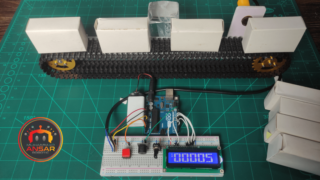
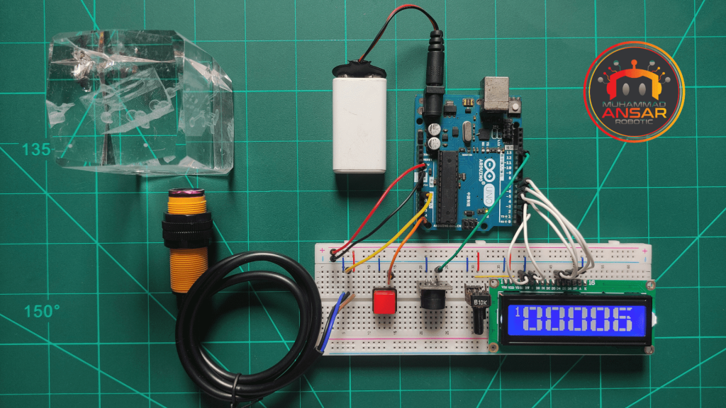
Hardware Testing
In order to verify the circuit’s practical functioning, actual components are used during the hardware testing step. By taking this step, you can be sure that the object counting system counts things in a particular environment properly and operates as intended. It also permits changes and fine-tuning in light of pragmatic factors.
Conclusion
To sum up, the Digital Object Counter with Arduino offers a flexible and effective way to automate counting in a range of applications. This blog article walks enthusiasts through the whole system construction process, including all the important details, from hardware testing to component needs. People may get significant understanding into object counting automation with Arduino technology by comprehending and putting this project into practice.


Leave a Reply