
Vehicle Speed Detector Using Arduino And IR Sensor

Introduction
Using Arduino and IR sensors to create a car speed detector might be an interesting and useful project in the field of traffic monitoring and safety. This blog post will walk you through the process of constructing an LCD display, an Arduino Uno, and infrared sensors to create a vehicle speed detector. You’ll have a working speed detection system at the conclusion of the project, which might be useful for personal projects or traffic management.
Components Required
- Solderless Breadboard x 2
- Arduino UNO
- IR Sensor x 2
- 16×2 LCD Display
- 100R Resistor
- 4.7k Resistor
- 1k Resistor
- Male to Male Jumper Wires
- Battery Clip
- 9V Battery
Proteus Simulation
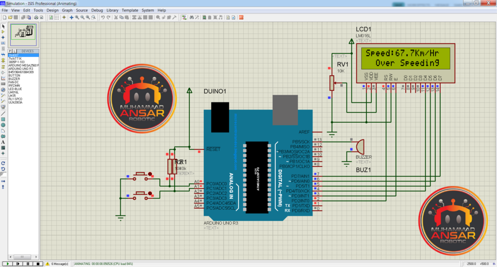
An Arduino UNO functions as the core processing unit in the Proteus 7 simulation for the Car Speed Detector project. Two push buttons mimic the presence of a passing vehicle in place of infrared modules. Ten kilohm resistances are attached to these buttons, which are configured as pull-ups by connecting them to the A0 and A1 pins. The device incorporates a 16 x 2 LCD display and a buzzer to give both visual and auditory feedback. In order to initiate the simulation, one must build a hex file from the Arduino code by going to ‘Sketch’ and choosing ‘Export Combined Binary.’ Two hex files are generated in the same folder as the code file upon compilation. The Arduino UNO is chosen once more in the simulation, and the matching hex file is loaded. A welcome message stating that no cars have been spotted appears on the LCD when the simulation starts. When a car crosses the first sensor, the LCD indicates “Searching,” and when it reaches the second sensor, the speed is computed and shown. The speed in kilometers per hour is displayed on the LCD, demonstrating how well the simulation simulates the speed detecting procedure. Furthermore, a check is incorporated to identify speeds beyond 50 kilometers per hour, which results in the LCD displaying ‘Over Speeding’ and the buzzer sounding for three seconds.
Circuit Diagram
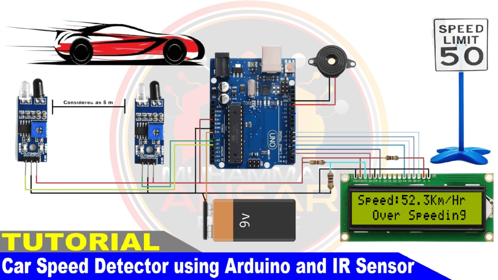
An Arduino UNO is key to the Car Speed Detector project’s circuit design. A buzzer is attached to pin 13 of the Arduino to function as an audio signal. The system simulates the presence of a vehicle with the help of two integrated infrared sensors. A nine-volt battery powers the device, and a 16 x 2 LCD is used to show the speed and status data. A 4.7-kilohm pull-up resistor and a 1-kilohm pull-down resistor are installed on the LCD’s contrast setting pin. The anode (pin number 15) and cathode (pin number 16) of the backlight are linked to 5 volts via a 100-ohm resistor. The ground is directly connected to the cathode pin. The first line of the LCD’s display shows the speed, while the second line indicates the status (i.e., whether the speed is within acceptable bounds or exceeds them). The circuit also has a mechanism for adjusting contrast to provide the best possible visibility on the LCD panel. The hardware for the Car Speed Detector project is constructed in accordance with this detailed circuit design.
Arduino IDE Code
#include<LiquidCrystal.h>
LiquidCrystal lcd(2, 3, 4, 5, 6, 7);

int timer1;
int timer2;

float Time;

int flag1 = 0;
int flag2 = 0;

float distance = 5.0;
float speed;

int ir_s1 = A0;
int ir_s2 = A1;

int buzzer = 13;

void setup(){
  pinMode(ir_s1, INPUT);
  pinMode(ir_s2, INPUT);
  pinMode(buzzer, OUTPUT);

  lcd.begin(16,2);
  lcd.clear();
  lcd.setCursor(0,0);
  lcd.print(" WELCOME To  My ");
  lcd.setCursor(0,1);
  lcd.print("YouTube  Channel");
  delay(2000);
  lcd.clear();
}

void loop() {
if(digitalRead (ir_s1) == LOW && flag1==0){timer1 = millis(); flag1=1;}

if(digitalRead (ir_s2) == LOW && flag2==0){timer2 = millis(); flag2=1;}

if (flag1==1 && flag2==1){
     if(timer1 > timer2){Time = timer1 - timer2;}
else if(timer2 > timer1){Time = timer2 - timer1;}
 Time=Time/1000;//convert millisecond to second
 speed=(distance/Time);//v=d/t
 speed=speed*3600;//multiply by seconds per hr
 speed=speed/1000;//division by meters per Km
}

if(speed==0){
lcd.setCursor(0, 1);
if(flag1==0 && flag2==0){lcd.print("No car  detected");}
                    else{lcd.print("Searching...    ");}
}
else{
    lcd.clear();
    lcd.setCursor(0, 0);
    lcd.print("Speed:");
    lcd.print(speed,1);
    lcd.print("Km/Hr  ");
    lcd.setCursor(0, 1);
  if(speed > 50){lcd.print("  Over Speeding  "); digitalWrite(buzzer, HIGH);}
            else{lcd.print("  Normal Speed   "); }
    delay(3000);
    digitalWrite(buzzer, LOW);
    speed = 0;
    flag1 = 0;
    flag2 = 0;
 }
}
Explanation
The Car Speed Detector project’s complex Arduino code makes effective use of a buzzer, two infrared sensors, and a 16 x 2 LCD display. The code first loads the LCD’s LiquidCrystal library. It then initializes the pins (2, 3, 4, 5, 6, 7) and a number of other variables, including timers, flags, distance, and speed. The code initializes components and configures pins in the void setup() section. The first welcome message appears on the LCD after it is configured. The void loop() portion computes the speed, the time it takes an automobile to drive between two sensors, and the state of the IR sensors continually. In addition to “No car detected,” “Searching,” and the computed speed and status (normal or over speeding) are shown live on the LCD. In the event of exceeding the speed limit, the buzzer sounds. In order to provide real-time information regarding vehicle speed and status on the LCD, the code presents an effective approach for capturing and processing sensor data. The uploading procedure to the Arduino board is described in the last portion of the code.
Hardware Testing
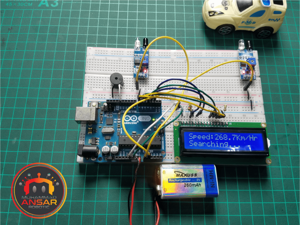
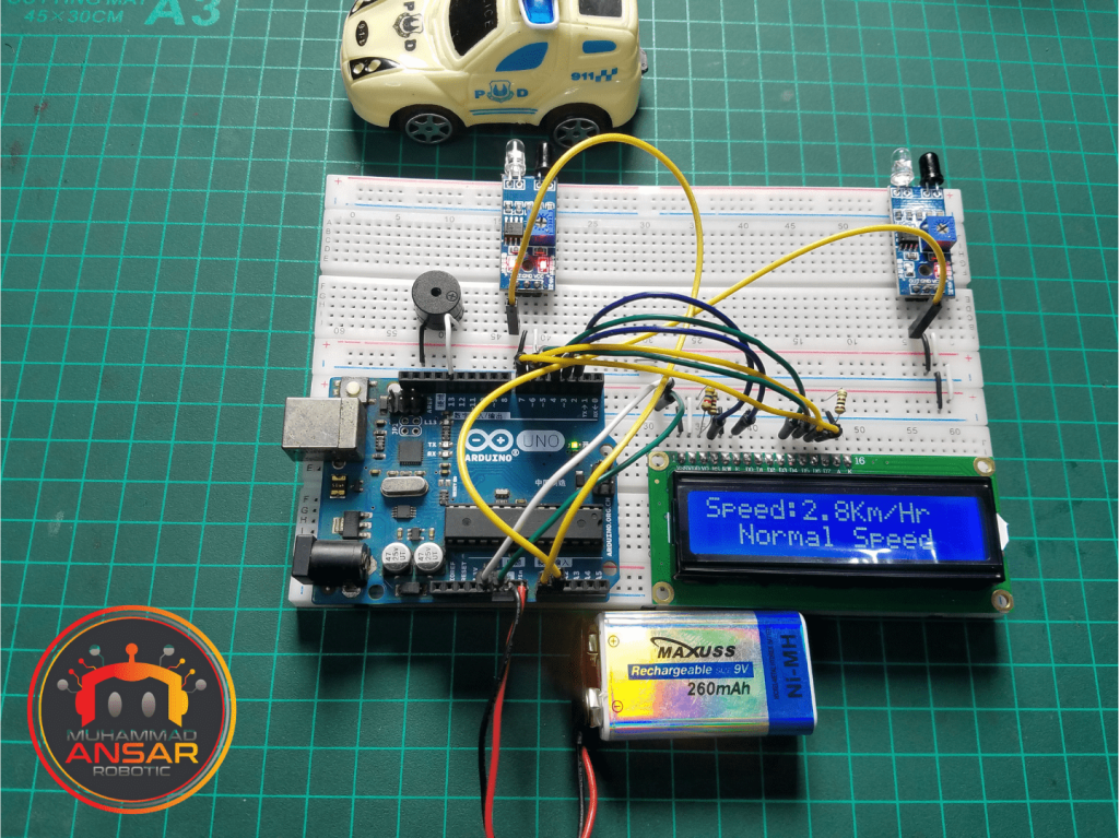
Hardware testing may begin when the Arduino code has been uploaded and the circuit has been put together on the solderless breadboard in accordance with the circuit design. In order to test the speed detector’s operation, a moving object—like a toy car—must be placed in front of the infrared sensors. The project should have been successfully executed if the LCD display shows the passing object’s speed appropriately.
Conclusion
In conclusion, constructing a car speed detector using an Arduino board and infrared sensors offers a practical introduction to integrating hardware and software. This project provides an introduction to sensor technology and microcontroller programming, which may be used for educational, hobbyist, or traffic management applications. The adaptability of Arduino in coming up with creative solutions for problems encountered in the real world is demonstrated by its ability to detect and monitor vehicle speed utilizing easily accessible components.


Leave a Reply