
Arduino Based 4 Way Traffic Signal Control
Introduction
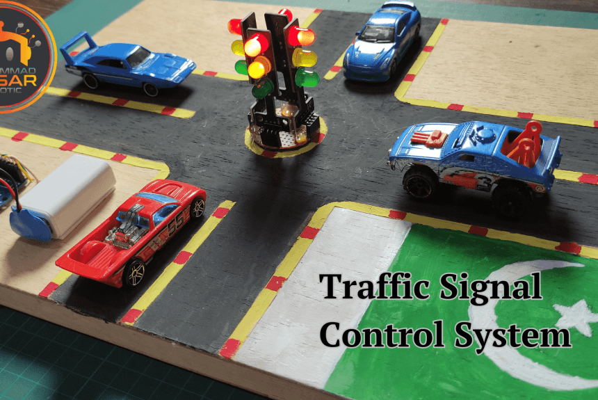
MArobotics introduces a new “Arduino UNO Based 4 Way Traffic Signal Control” system designed for effective traffic management. This project uses the Arduino UNO to synchronize and manage a four-way traffic signal, giving a complete solution for traffic crossings. MArobotics’ implementation focuses on improving road safety and traffic flow by precisely timing and sequencing traffic lights. The system’s adaptability enables easy integration into urban infrastructure, making it an invaluable tool for controlling junctions and encouraging a smoother and safer traffic experience. This project provides a realistic knowledge of how traffic lights work and can be controlled using programmable electronics by utilizing an Arduino Uno and specialized traffic light modules.
Components Required
- Dotted Veroboard
- Arduino UNO
- Traffic Light Module x 4
- Male Header
- Female Header
- On/Off Switch
- Battery Clip
- 9V Battery
Proteus Simulation
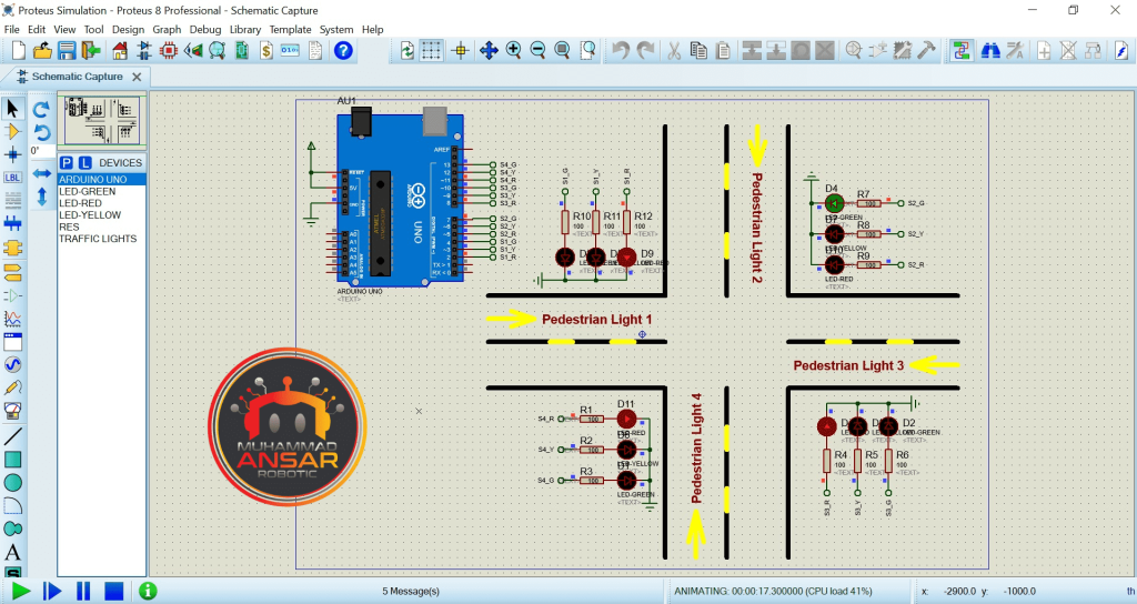
An Arduino UNO, four traffic light modules, and related parts are used in the setup of the “Traffic Light Control System using Arduino” simulation. Each traffic signal pole has three LEDs: red, yellow, and green; moreover, each module has 100 kilo ohm resistors. In order to replicate a realistic traffic signal sequence, the Arduino UNO controls the LEDs. Proteus integrates the hex file produced by the Arduino IDE into the simulation program. Every signal pole performs in a predefined order during the simulation. The green LED illuminates for a predetermined amount of time after the red and yellow LEDs do so for one second each. A simulated traffic flow is produced by synchronizing the time of each signal pole. Before moving on to the hardware implementation, users may witness how the traffic light control system operates thanks to this thorough simulation. The process repeats itself, proving that a four-way traffic light system is well controlled.
Circuit Diagram
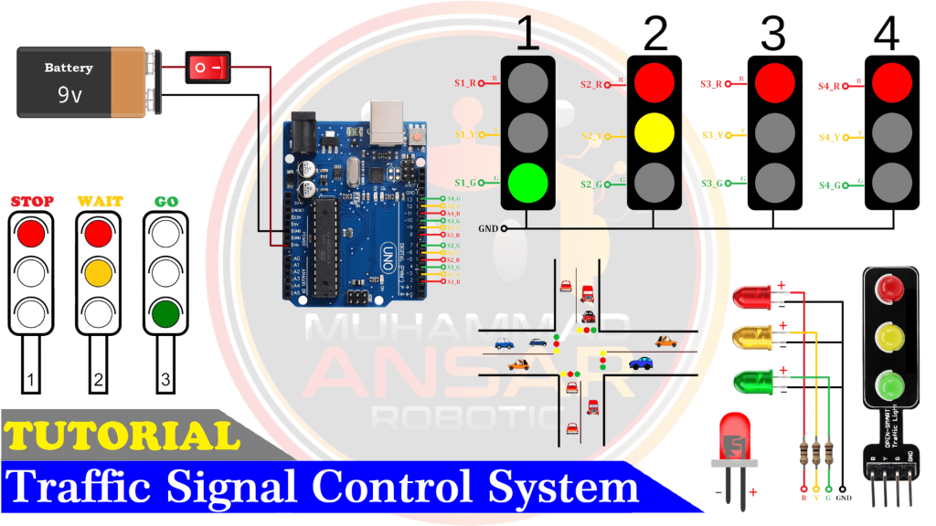
The power source in the circuit schematic is a 9-volt battery that can be turned on and off using a switch. The configuration includes the Arduino UNO, the central component. The Arduino is linked to four traffic light modules, each of which represents a signal pole. Each traffic light module’s circuitry has 100-ohm resistances connected in series with the red, yellow, and green LEDs’ positive terminals. Each signal pole’s LEDs are wired to a distinct pin on the Arduino. For example, the LEDs of pole 1 are allocated pins 2, 3, and 4, while pole 2 is assigned pins 5, 6, and 7. Pins 8, 9, and 10 correspond to pole 3, and pins 11, 12, and 13 correspond to pole 4. The Arduino’s ground pin is linked to the common ground pins of each of the four modules.
Arduino IDE Code
#define s1_r 2 // Green  Led Pin Out
#define s1_y 3 // Yellow Led Pin Out
#define s1_g 4 // Red    Led Pin Out

#define s2_r 5 // Green  Led Pin Out
#define s2_y 6 // Yellow Led Pin Out
#define s2_g 7 // Red    Led Pin Out

#define s3_r 8 // Green  Led Pin Out
#define s3_y 9 // Yellow Led Pin Out
#define s3_g 10// Red    Led Pin Out

#define s4_r 11// Green  Led Pin Out
#define s4_y 12// Yellow Led Pin Out
#define s4_g 13// Red    Led Pin Out

int G1_time = 4;  //Set singl 1 open time
int G2_time = 6;  //Set singl 2 open time
int G3_time = 8;  //Set singl 3 open time
int G4_time = 10; //Set singl 4 open time

int Y_time = 1; //Set All singl Wait time

int Mode=0;
int Second=0;
word MilliSecond=0;

void setup(){ // put your setup code here, to run once

pinMode(s1_r, OUTPUT);
pinMode(s1_y, OUTPUT);
pinMode(s1_g, OUTPUT);

pinMode(s2_r, OUTPUT);
pinMode(s2_y, OUTPUT);
pinMode(s2_g, OUTPUT);

pinMode(s3_r, OUTPUT);
pinMode(s3_y, OUTPUT);
pinMode(s3_g, OUTPUT);

pinMode(s4_r, OUTPUT);
pinMode(s4_y, OUTPUT);
pinMode(s4_g, OUTPUT);

noInterrupts();         // disable all interrupts
TCCR1A = 0;             // set entire TCCR1A register to 0  //set timer1 interrupt at 1kHz  // 1 ms
TCCR1B = 0;             // same for TCCR1B
TCNT1  = 0;             // set timer count for 1khz increments
OCR1A = 1999;           // = (16*10^6) / (1000*8) - 1
//had to use 16 bit timer1 for this bc 1999>255, but could switch to timers 0 or 2 with larger prescaler
// turn on CTC mode
TCCR1B |= (1 << WGM12); // Set CS11 bit for 8 prescaler
TCCR1B |= (1 << CS11);  // enable timer compare interrupt
TIMSK1 |= (1 << OCIE1A);
interrupts();           // enable

Second = Y_time;
yellow(Mode);
delay(100); // Waiting for a while
}

void loop(){

if(Mode==0 && Second==0){Second=G1_time; Mode=1; Open(Mode);}
if(Mode==1 && Second==0){Second=Y_time;  Mode=2; yellow(Mode);}

if(Mode==2 && Second==0){Second=G2_time; Mode=3; Open(Mode);}
if(Mode==3 && Second==0){Second=Y_time;  Mode=4; yellow(Mode);}

if(Mode==4 && Second==0){Second=G3_time; Mode=5; Open(Mode);}
if(Mode==5 && Second==0){Second=Y_time;  Mode=6; yellow(Mode);}

if(Mode==6 && Second==0){Second=G4_time; Mode=7; Open(Mode);}
if(Mode==7 && Second==0){Second=Y_time;  Mode=0; yellow(Mode);}

delay(10);
}

void yellow(int y){
digitalWrite(s1_r, 1);
if(y==0){digitalWrite(s1_y, 1);}
       else{digitalWrite(s1_y, 0);}
digitalWrite(s1_g, 0);

digitalWrite(s2_r, 1);
if(y==2){digitalWrite(s2_y, 1);}
       else{digitalWrite(s2_y, 0);}
digitalWrite(s2_g, 0);

digitalWrite(s3_r, 1);
if(y==4){digitalWrite(s3_y, 1);}
       else{digitalWrite(s3_y, 0);}
digitalWrite(s3_g, 0);

digitalWrite(s4_r, 1);
if(y==6){digitalWrite(s4_y, 1);}
       else{digitalWrite(s4_y, 0);}
digitalWrite(s4_g, 0);
}

void Open(int Set){

digitalWrite(s1_y, 0);
if(Set==1){digitalWrite(s1_g, 1); digitalWrite(s1_r, 0);}
       else{digitalWrite(s1_g, 0); digitalWrite(s1_r, 1);}

digitalWrite(s2_y, 0);
if(Set==3){digitalWrite(s2_g, 1); digitalWrite(s2_r, 0);}
       else{digitalWrite(s2_g, 0); digitalWrite(s2_r, 1);}

digitalWrite(s3_y, 0);
if(Set==5){digitalWrite(s3_g, 1); digitalWrite(s3_r, 0);}
       else{digitalWrite(s3_g, 0); digitalWrite(s3_r, 1);}

digitalWrite(s4_y, 0);
if(Set==7){digitalWrite(s4_g, 1); digitalWrite(s4_r, 0);}
       else{digitalWrite(s4_g, 0); digitalWrite(s4_r, 1);}

}

ISR(TIMER1_COMPA_vect){
MilliSecond++;
if(MilliSecond >= 1000){MilliSecond = 0;
       Second = Second-1;
 }
}
Explanation
The code given is for an Arduino microcontroller software that controls a series of LED traffic signal lights for four separate poles. Each pole has three LEDs, which stand for the red, yellow, and green signals, and these LEDs are attached to designated pins on the Arduino board. Variables for each signal’s open times are initialized by the code, along with a variable that indicates how long the yellow signal will last until turning green. There are further variables to monitor the current mode of operation, time in milliseconds, and seconds. The setup function sets the starting mode to 0 and initializes the timers and pin modes. The loop function, which cycles through several modes to regulate the traffic signals, is where the core logic is implemented. The software use timers to control the length of each state, with each mode denoting a distinct condition in the traffic light sequence. Depending on the current mode, the yellow and open routines are called to control the yellow and green LEDs, respectively. Open the code on Arduino IDE. Compile the code. Select the board as Arduino UNO. Then, select the port. After this, upload the code on the Arduino UNO.
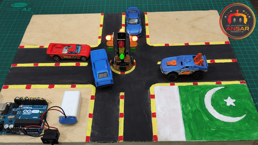
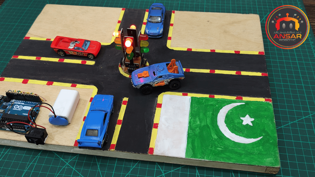
Hardware Testing
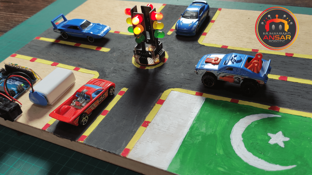
The circuit is physically implemented on the dotted Veroboard during the hardware testing step. Users may verify the project’s operation in the real world by connecting the Arduino, traffic light modules, and other components in accordance with the circuit diagram. The practical experience gained from simulation and code creation helps to cement the principles acquired.

Conclusion
To sum up, the “Traffic Light Control System using Arduino” project offers a perceptive look at how electronics are integrated into commonplace processes. Learners and enthusiasts acquire important information about circuit design, microcontroller programming, and real-world application. For people curious in both electronics and smart city technology, this project is a great place to start, as traffic lights are an essential part of urban infrastructure. Development and evaluation of the project provides practical experience that improves abilities that may be used to a variety of electronic systems.
4 responses to “Arduino Based 4 Way Traffic Signal Control”

interrupts(); // enable
Second = Y_time;
yellow(Mode);
delay(100); // Waiting for a while
}void loop(){
if(Mode==0 && Second==0){Second=G1_time; Mode=1; Open(Mode);}
if(Mode==1 && Second==0){Second=Y_time; Mode=2; yellow(Mode);}if(Mode==2 && Second==0){Second=G2_time; Mode=3; Open(Mode);}
if(Mode==3 && Second==0){Second=Y_time; Mode=4; yellow(Mode);}if(Mode==4 && Second==0){Second=G3_time; Mode=5; Open(Mode);}
if(Mode==5 && Second==0){Second=Y_time; Mode=6; yellow(Mode);}if(Mode==6 && Second==0){Second=G4_time; Mode=7; Open(Mode);}
if(Mode==7 && Second==0){Second=Y_time; Mode=0; yellow(Mode);}delay(10);
}void yellow(int y){
digitalWrite(s1_r, 1);
if(y==0){digitalWrite(s1_y, 1);}
else{digitalWrite(s1_y, 0);}
digitalWrite(s1_g, 0);digitalWrite(s2_r, 1);
if(y==2){digitalWrite(s2_y, 1);}
else{digitalWrite(s2_y, 0);}
digitalWrite(s2_g, 0);digitalWrite(s3_r, 1);
if(y==4){digitalWrite(s3_y, 1);}
else{digitalWrite(s3_y, 0);}
digitalWrite(s3_g, 0);digitalWrite(s4_r, 1);
if(y==6){digitalWrite(s4_y, 1);}
else{digitalWrite(s4_y, 0);}
digitalWrite(s4_g, 0);
}void Open(int Set){
digitalWrite(s1_y, 0);
if(Set==1){digitalWrite(s1_g, 1); digitalWrite(s1_r, 0);}
else{digitalWrite(s1_g, 0); digitalWrite(s1_r, 1);}digitalWrite(s2_y, 0);
if(Set==3){digitalWrite(s2_g, 1); digitalWrite(s2_r, 0);}
else{digitalWrite(s2_g, 0); digitalWrite(s2_r, 1);}digitalWrite(s3_y, 0);
if(Set==5){digitalWrite(s3_g, 1); digitalWrite(s3_r, 0);}
else{digitalWrite(s3_g, 0); digitalWrite(s3_r, 1);}Bhai a jo program error dikhara hai
Thank you
Thank you,
welcome


4 thoughts on “Arduino Based 4 Way Traffic Signal Control”
 AIYAN says:
interrupts(); // enable
Second = Y_time;
yellow(Mode);
delay(100); // Waiting for a while
}void loop(){
if(Mode==0 && Second==0){Second=G1_time; Mode=1; Open(Mode);}
if(Mode==1 && Second==0){Second=Y_time; Mode=2; yellow(Mode);}if(Mode==2 && Second==0){Second=G2_time; Mode=3; Open(Mode);}
if(Mode==3 && Second==0){Second=Y_time; Mode=4; yellow(Mode);}if(Mode==4 && Second==0){Second=G3_time; Mode=5; Open(Mode);}
if(Mode==5 && Second==0){Second=Y_time; Mode=6; yellow(Mode);}if(Mode==6 && Second==0){Second=G4_time; Mode=7; Open(Mode);}
if(Mode==7 && Second==0){Second=Y_time; Mode=0; yellow(Mode);}delay(10);
}void yellow(int y){
digitalWrite(s1_r, 1);
if(y==0){digitalWrite(s1_y, 1);}
else{digitalWrite(s1_y, 0);}
digitalWrite(s1_g, 0);digitalWrite(s2_r, 1);
if(y==2){digitalWrite(s2_y, 1);}
else{digitalWrite(s2_y, 0);}
digitalWrite(s2_g, 0);digitalWrite(s3_r, 1);
if(y==4){digitalWrite(s3_y, 1);}
else{digitalWrite(s3_y, 0);}
digitalWrite(s3_g, 0);digitalWrite(s4_r, 1);
if(y==6){digitalWrite(s4_y, 1);}
else{digitalWrite(s4_y, 0);}
digitalWrite(s4_g, 0);
}void Open(int Set){
digitalWrite(s1_y, 0);
if(Set==1){digitalWrite(s1_g, 1); digitalWrite(s1_r, 0);}
else{digitalWrite(s1_g, 0); digitalWrite(s1_r, 1);}digitalWrite(s2_y, 0);
if(Set==3){digitalWrite(s2_g, 1); digitalWrite(s2_r, 0);}
else{digitalWrite(s2_g, 0); digitalWrite(s2_r, 1);}digitalWrite(s3_y, 0);
if(Set==5){digitalWrite(s3_g, 1); digitalWrite(s3_r, 0);}
else{digitalWrite(s3_g, 0); digitalWrite(s3_r, 1);}Bhai a jo program error dikhara hai
- Liao Yuping says:
Thank you
- Liao Yuping says:
Thank you,
Leave a Reply