
Stepper Motor Speed Controller Using A4988 Stepper Motor Driver

Introduction
With the combination of an Arduino Uno and an A4988 Stepper Motor Driver, the Stepper Motor Speed Controller project offers an interesting look into the field of motor control. For those who enjoy electronics, this project offers a thorough grasp of stepper motor performance and control mechanisms, facilitating a hands-on learning experience. Using essential parts like a Nema 17 stepper motor, push buttons, and a 16×2 LCD display, the
Components Required
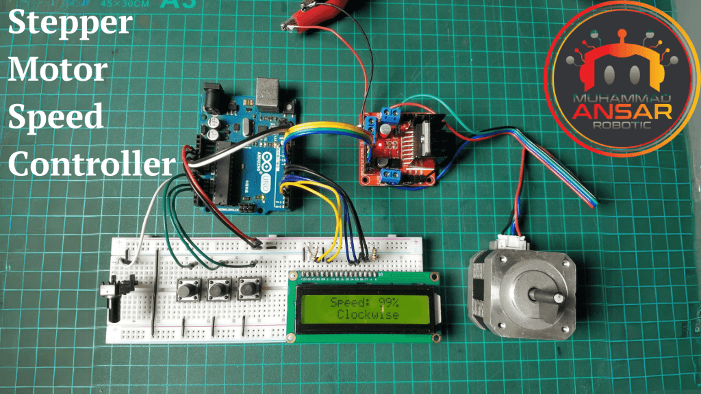
Circuit Diagram
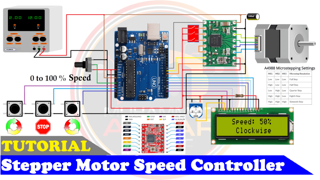
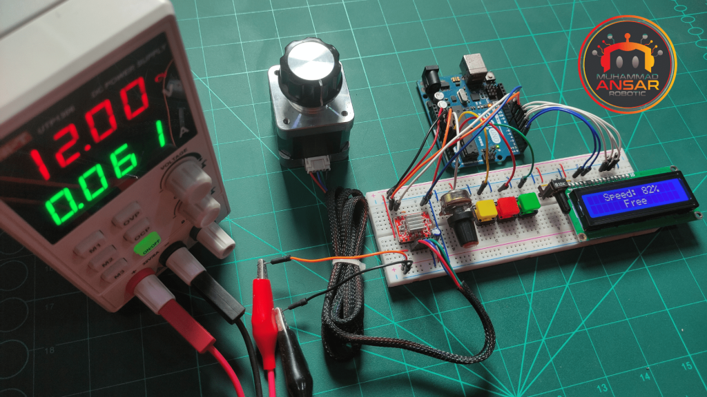
The “Stepper Motor Speed Controller” project’s circuit schematic shows a thoroughly constructed configuration intended to provide exact control over a stepper motor. A reliable 12V, 2A power source lays the basis and supplies sufficient power for the system. An Arduino Uno acts as the circuit’s central controller, coordinating every aspect of functioning. The 10k variable resistor is an essential part that allows for precise control of motor speed. Three well placed push buttons enable user interaction. These buttons are essential for starting anticlockwise rotation, stopping the motor, and permitting clockwise rotation. The addition of a 10k potentiometer for contrast adjustment in conjunction with a 16×2 LCD display improves the user interface by enabling real-time motor speed monitoring and status updates. The A4988 Stepper Motor Driver, which is well known for its ability to manage the Nema 17 stepper motor with a 2A capacity, is at the center of the motor control system. In order to provide a steady power supply, the circuit also includes a capacitor. The stepper motor, Arduino, and driver are carefully connected to ensure smooth operation and communication.
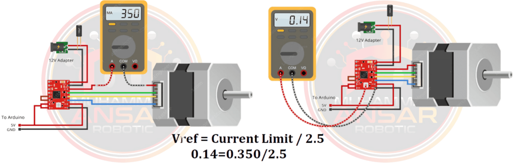
Vref Voltage Setting Current Limit for A4988 with Multimeter
Arduino IDE Code
#include <LiquidCrystal.h>
LiquidCrystal lcd(2, 3, 4, 5, 6, 7);

#define potentiometer  A0  //10k Variable Resistor
#define bt_F A1 // Clockwise Button
#define bt_S A2 // Stop Button
#define bt_B A3 // Anticlockwise Button

#define dirPin  8  //8Pin  of Arduino--Direction of stepper motor driver
#define stepPin 9  //9Pin  of Arduino--Step of stepper motor driver
#define enPin   10 //10Pin of Arduino--Enabled of stepper motor driver

int read_ADC;
int Speed_LCD, Speed_Delay;
int Mode=1, flag=0;

void setup() { // put your setup code here, to run once

pinMode(potentiometer, INPUT); // declare potentiometer as input

pinMode(bt_F, INPUT_PULLUP); // declare bt_F as input
pinMode(bt_S, INPUT_PULLUP); // declare bt_S as input
pinMode(bt_B, INPUT_PULLUP); // declare bt_B as input

pinMode(dirPin,  OUTPUT); // declare as output for Direction of stepper motor driver
pinMode(stepPin, OUTPUT); // declare as output for Step of stepper motor driver
pinMode(enPin,   OUTPUT); // declare as output for Enabled of stepper motor driver

lcd.begin(16,2);
lcd.setCursor(0,0);
lcd.print(" WELCOME To  My ");
lcd.setCursor(0,1);
lcd.print("YouTube  Channel");
delay(2000); // Waiting for a while
lcd.clear();
}

void loop() {

read_ADC = analogRead(potentiometer); // read analogue to digital value 0 to 1023
Speed_Delay = map(read_ADC, 0, 1023, 5000, 10); //value map for Microstep resolution Delay
Speed_LCD = map(read_ADC, 0, 1023, 0, 100); //value map to Display on the LCD

lcd.setCursor(0,0);
lcd.print("   Speed: ");
lcd.print(Speed_LCD);
lcd.print("%  ");

if(digitalRead (bt_F) == 0){Mode = 2; digitalWrite(enPin, LOW);} //For Clockwise

if(digitalRead (bt_S) == 0){ //For Stop
if(flag==0){flag=1;
 if(Mode>1)Mode=1;
      else{Mode=!Mode;
      if(Mode==0)digitalWrite(enPin, HIGH);
            else digitalWrite(enPin, LOW);
      }
delay(100);
 }
}else{flag=0;}

if(digitalRead (bt_B) == 0){Mode = 3; digitalWrite(enPin, LOW);} //For Anticlockwise

lcd.setCursor(0,1);

     if(Mode==0)lcd.print("      Free      ");
else if(Mode==1)lcd.print("      Stop      ");
else if(Mode==2)lcd.print("    Clockwise   ");
else if(Mode==3)lcd.print("  Anticlockwise ");

if(Speed_LCD>0 && Mode>1){

     if(Mode==2)digitalWrite(dirPin, LOW);// Stepper motor rotates CW (Clockwise)
           else digitalWrite(dirPin, HIGH);// Stepper motor rotates CCW (Anticlockwise)

digitalWrite(stepPin, HIGH);
delayMicroseconds(Speed_Delay);
digitalWrite(stepPin, LOW);
delayMicroseconds(Speed_Delay);
}

}
Explanation
The library required to interface with a liquid crystal display (LCD) for output is first included in the code. It sets the starting pins for a number of parts, including the stepper motor driver, LCD, potentiometer, and push buttons. The enable, step, and direction pins are part of the stepper motor driver pins. The setup function initializes the LCD, sets the pins’ input and output modes, and shows a welcome message. The loop function, which reads and maps the analog value from the potentiometer to control the stepper motor’s speed, implements the core functionality. Additionally, the code analyzes the digital inputs from push buttons to identify the operating mode (free, stop, anticlockwise, or clockwise). The stepper motor movement is thus controlled by the mode and speed parameters, which also refresh the LCD display with pertinent data. The code incorporates logic to halt the motor and adjust the display in accordance with the mode of operation, and conditional statements are used to handle various scenarios. Lastly, the code contains instructions on how to use the Arduino IDE to upload to an Arduino board. All in all, the code offers a complete stepper motor control system that is reliant on human inputs via a push button and potentiometer.
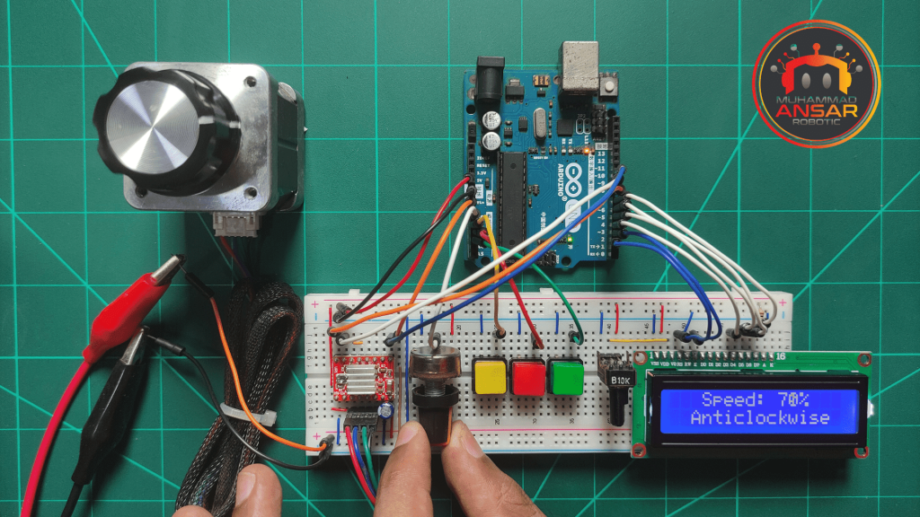
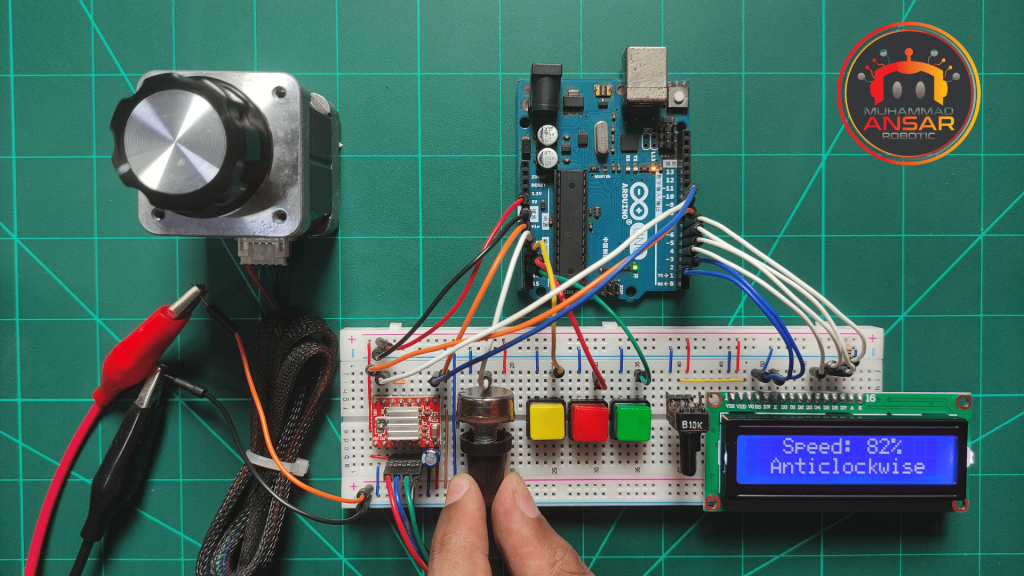
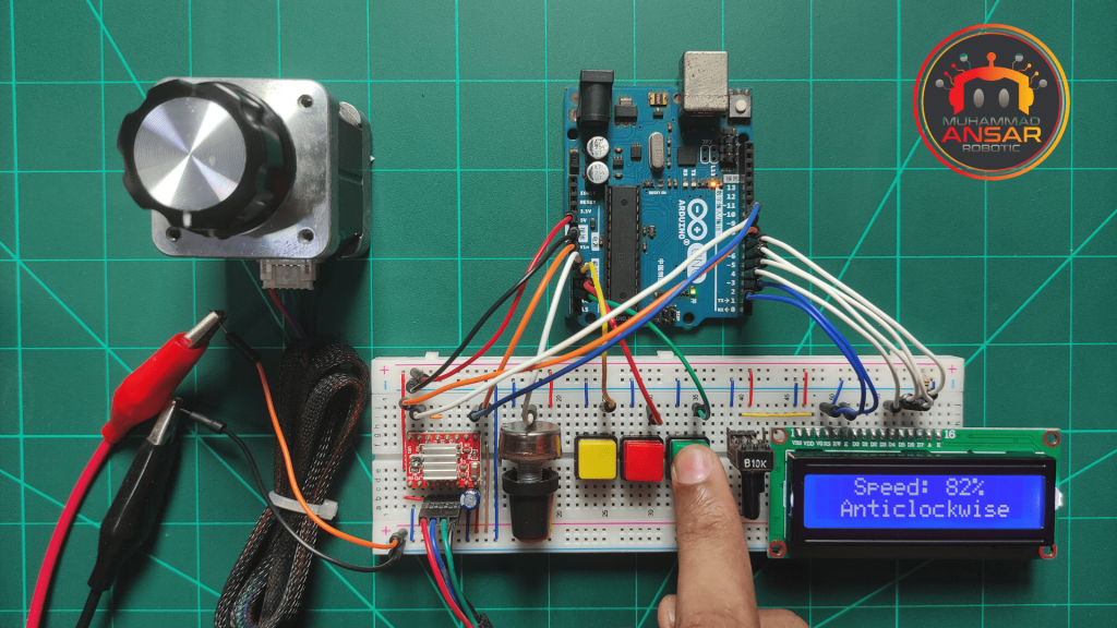
Hardware Testing
This project’s hardware configuration includes push buttons, a potentiometer, a stepper motor, and a liquid crystal display (LCD). The three primary pins of a stepper motor driver—direction, step, and enable—are responsible for controlling the stepper motor. These pins are linked to certain Arduino board digital pins. Three push buttons are also included for halting the motor, rotating the motor in an anticlockwise direction, and rotating the clockwise direction. A potentiometer is attached to an analog pin for speed control. By default, the stepper motor runs in full-step mode. Nevertheless, the stepper motor driver’s MS1 pin can receive 5 volts, which causes the operation to transition to half-step mode. The motor travels one step for every two pulses while in half-step mode, as opposed to one step for every pulse when in full-step mode. With this modification, when 5 volts are given to the MS1 pin, the stepper motor’s speed is effectively reduced to 50% of its initial speed. This speed variation is accomplished by varying the length of pulses that are transmitted to the stepper motor driver, which affects the step rate and, in turn, the rotational speed of the motor. In order to display data such as the motor’s current condition, speed %, and direction of rotation (clockwise, counterclockwise, stop, or free), the project also includes an LCD. The coding and hardware setup enable the stepper motor to operate dynamically and under human control.
Conclusion
To sum up, the Arduino project that has been described integrates hardware and software components to produce a flexible stepper motor control system. Through the use of a potentiometer and push buttons, the code allows for user-defined modes such as halting the motor and rotating the motor in both clockwise and counterclockwise directions. The Arduino board and other components may be seamlessly integrated thanks to the hardware configuration, which includes the stepper motor driver and related pins. The technology offers immediate insight on the motor’s speed, mode, and state by integrating a liquid crystal display.
One response to “Stepper Motor Speed Controller Using A4988 Stepper Motor Driver”

AslamAlykum Muhammad Ansar
Very good on your YouTube videos.
I have a suggestion for you to improve the smoothness of your stepper motor.In your code:
digitalWrite(stepPin, HIGH);
delayMicroseconds(Speed_Delay);
digitalWrite(stepPin, LOW);
delayMicroseconds(Speed_Delay);You can change the first delay to a minimum number of microseconds that your motor will run at. Keep the second delay the same as you have it. It won’t affect the speed of your motor but will make it run much quieter and smoother. For example, according to your code the minimum is 10, you can change your code to:
digitalWrite(stepPin, HIGH);
delayMicroseconds(10); //Minimum number of microseconds that your motor will run at to make it run smooth.
digitalWrite(stepPin, LOW);
delayMicroseconds(Speed_Delay);Best regards,
Mohammad Afzal


Related Posts
Stepper Motor Speed Controller Using Arduino And L298 Motor Driver
One thought on “Stepper Motor Speed Controller Using A4988 Stepper Motor Driver”
 MOHAMMAD AFZAL says:
AslamAlykum Muhammad Ansar
Very good on your YouTube videos.
I have a suggestion for you to improve the smoothness of your stepper motor.In your code:
digitalWrite(stepPin, HIGH);
delayMicroseconds(Speed_Delay);
digitalWrite(stepPin, LOW);
delayMicroseconds(Speed_Delay);You can change the first delay to a minimum number of microseconds that your motor will run at. Keep the second delay the same as you have it. It won’t affect the speed of your motor but will make it run much quieter and smoother. For example, according to your code the minimum is 10, you can change your code to:
digitalWrite(stepPin, HIGH);
delayMicroseconds(10); //Minimum number of microseconds that your motor will run at to make it run smooth.
digitalWrite(stepPin, LOW);
delayMicroseconds(Speed_Delay);Best regards,
Mohammad Afzal
Leave a Reply