
Stepper Motor Speed Controller Using Arduino And L298 Motor Driver

Introduction
Stepper motors are extensively employed in many different applications, and speed control is essential to accuracy and effectiveness. In this project, we will explore the use of an Arduino and the L298 Motor Driver to create a Stepper Motor Speed Controller. We’ll be able to effortlessly manage the stepper motor’s speed by integrating an intuitive interface with push buttons and a 16×2 LCD display. This project demonstrates a complex technique for regulating the speed and rotation of a stepper motor, resulting in accurate motor motions. Users may perform dynamic speed modifications using Arduino and the L298 motor driver, making it ideal for robotics, automation, and other projects that need precision motor control. MArobotics’ implementation offers a simple and effective option for anyone looking to include stepper motors into their projects with simplicity and precision.
Components Required
- Solderless Breadboard
- Arduino UNO
- 16×2 LCD Display
- Push Button x 3
- L298 Motor Driver
- Nema 17 Stepper Motor
- 10k Variable Resistor
- 100R Resistor
- 4.7k Resistor
- 1k Resistor
- Male to Male Jumper Wires
- Male to Female Jumper Wires
- 12V 2Amp Power Adapter
Proteus Simulation
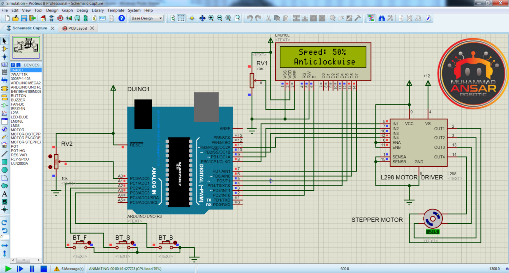
The Stepper Motor Speed Controller project’s simulation file has all the parts precisely placed to mimic the hardware configuration. An Arduino UNO, a 10k potentiometer, three push buttons (BT_F, BT_B, and stop), a 16×2 LCD, an L298 motor driver, and a Nema 17 stepper motor are all included in the simulation using Proteus 8. Together, these parts make up the project’s core and allow for speed control and monitoring of the stepper motor.
By simulating actual events, the simulation attempts to provide users an understanding of how a stepper motor behaves in various settings. Interactive control may be achieved with the help of the stop button, the clockwise (BT_F) and anticlockwise (BT_B) buttons. The rotation speed of the motor is affected by the potentiometer’s adjustments to the speed variable.
Generate the hex-file from the given Arduino code in order to execute the simulation. A thorough virtual environment for testing and validation is created by the LCD, which shows real-time data regarding the motor’s speed and condition.
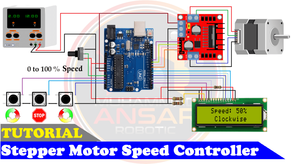
Circuit Diagram
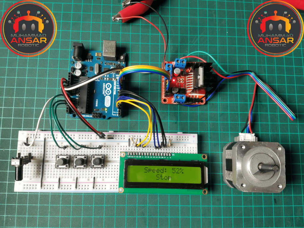
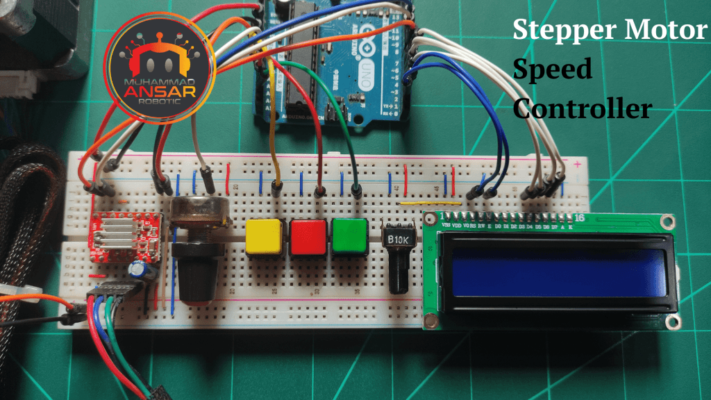
The first part in the circuit diagram is a power supply that supplies 12 volts and 2 amps. Then, as a central control unit, an Arduino UNO is integrated into the circuit. An analog input is enabled by a 1k potentiometer that is connected to the Arduino UNO, especially to the A0 pin. Three push buttons are then included into the circuit to allow for human contact. Moving on to the components, information is displayed on a 16×2 LCD panel. The LCD’s first line shows a variable that represents speed, and the next line gives updates on the situation as it is right now. Interestingly, a 4.7k resistor must be connected between the positive and ground pins of the LCD in order to activate the contrast setting. Regarding the LCD backlighting, pins 15 and 16 are used; pin 15 is the anode and pin 16 is the cathode. The positive connection to the anode is connected in series with a 100-ohm resistor. Subsequently, an L298 motor driver is included into the circuit to enable motor control. A stepper motor, which emphasizes accuracy in rotating motions, is connected to the motor driver. This thorough arrangement finishes the circuit design and prepares the groundwork for the hardware implementation that follows, which will be based on the schematic.
Arduino IDE Code
#include <LiquidCrystal.h>
LiquidCrystal lcd(2, 3, 4, 5, 6, 7);

#define potentiometer  A0  //10k Variable Resistor
#define bt_F A1 // Clockwise Button
#define bt_S A2 // Stop Button
#define bt_B A3 // Anticlockwise Button

#define in1 11 //Motor  L298 Pin in1
#define in2 10 //Motor  L298 Pin in2
#define in3 9  //Motor  L298 Pin in3
#define in4 8  //Motor  L298 Pin in4

int read_ADC;
int Speed_LCD;
int Speed;
int Step;
int Mode=0;

void setup() { // put your setup code here, to run once

pinMode(potentiometer, INPUT); // declare potentiometer as input

pinMode(bt_F, INPUT_PULLUP); // declare bt_F as input
pinMode(bt_S, INPUT_PULLUP); // declare bt_S as input
pinMode(bt_B, INPUT_PULLUP); // declare bt_B as input

pinMode(in1, OUTPUT); // declare as output for L298 Pin in1
pinMode(in2, OUTPUT); // declare as output for L298 Pin in2
pinMode(in3, OUTPUT); // declare as output for L298 Pin in3
pinMode(in4, OUTPUT); // declare as output for L298 Pin in4

lcd.begin(16,2);
lcd.setCursor(0,0);
lcd.print(" WELCOME To  My ");
lcd.setCursor(0,1);
lcd.print("YouTube  Channel");
delay(2000); // Waiting for a while
lcd.clear();
}

void loop() {

read_ADC = analogRead(potentiometer); // read analogue to digital value 0 to 1023
Speed = map(read_ADC, 0, 1023, 100, 0);
Speed_LCD = map(read_ADC, 0, 1023, 0, 100);


lcd.setCursor(0,0);
lcd.print("   Speed: ");
lcd.print(Speed_LCD);
lcd.print("%  ");

if(digitalRead (bt_F) == 0){Mode = 1;} //For Clockwise
if(digitalRead (bt_S) == 0){Mode = 0;} //For Stop
if(digitalRead (bt_B) == 0){Mode = 2;} //For Anticlockwise

lcd.setCursor(0,1);

if(Mode==0){ lcd.print("      Stop      ");}
if(Mode==1){ lcd.print("    Clockwise   ");}
if(Mode==2){ lcd.print("  Anticlockwise ");}

if(Speed_LCD>0){
if(Mode==1){
Step = Step+1;
if(Step>3){Step=0;}
call_Step(Step);// Stepper motor rotates CW (Clockwise)
}

if(Mode==2){
Step = Step-1;
if(Step<0){Step=3;}
call_Step(Step);// Stepper motor rotates CCW (Anticlockwise)
}

delay(Speed);
}


}

//The sequence of control signals for 4 control wires is as follows:
//Step C0 C1 C2 C3
//  1  1  0  1  0
//  2  0  1  1  0
//  3  0  1  0  1
//  4  1  0  0  1

void call_Step(int i){
    switch (i) {
      case 0:  // 1010
        digitalWrite(in1, HIGH);
        digitalWrite(in2, LOW);
        digitalWrite(in3, HIGH);
        digitalWrite(in4, LOW);
      break;
      case 1:  // 0110
        digitalWrite(in1, LOW);
        digitalWrite(in2, HIGH);
        digitalWrite(in3, HIGH);
        digitalWrite(in4, LOW);
      break;
      case 2:  //0101
        digitalWrite(in1, LOW);
        digitalWrite(in2, HIGH);
        digitalWrite(in3, LOW);
        digitalWrite(in4, HIGH);
      break;
      case 3:  //1001
        digitalWrite(in1, HIGH);
        digitalWrite(in2, LOW);
        digitalWrite(in3, LOW);
        digitalWrite(in4, HIGH);
      break;
    }
  }
Explanation
To begin with, the Liquid Crystal library is integrated to make communication with the 16×2 LCD easier. Then, pin assignments are set up for a number of components, such as the LCD pins 2 through 7, the potentiometer pin A0, the forward button pin A1 for BT_F, the stop button pin A2 for BT_S, the backward button pin A3 for BT_B, and the four pins for the L298 motor driver. In order to manage input readings and control settings, additional variables are initialized, including read_ADC, speed_LCD, speed, step, and mode. The pin configuration for the potentiometer and push buttons is described next, along with the setup function. The 16×2 LCD is initialized, and the L298 motor driver pins are configured for output mode. The LCD shows a brief welcome message before going into the main loop. The potentiometer’s analog pin is read inside the loop, and the results are transferred to the speed variable. The mode variable is adjusted based on the status of the push buttons (BT_F, BT_S, and BT_B), which in turn affects the status that is shown on the LCD. The motor may be made to rotate clockwise, counterclockwise, or halt depending on the mode. By executing certain motor steps in response to the input variable “i,” the call_step function allows for precise motor control. The mapped speed variable determines the delay at the end of the code, after which motor steps are executed. The narrator validates a successful upload in the last part, which offers instructions on how to upload the code to the Arduino board via the Arduino IDE.
In this Arduino code, the call_Step function is defined to control the sequence of signals sent to a stepper motor with a 4-wire configuration (in1, in2, in3, in4). Stepper motors typically have a specific sequence of control signals to achieve smooth and controlled rotation. The function uses a switch statement with four cases (0 to 3), each representing a step in the stepper motor sequence.
- Case ‘0’ corresponds to the binary sequence 1010, which energizes the motor coils in a specific order to achieve the first step in the stepper motor rotation.
- Case ‘1’ corresponds to the binary sequence 0110, representing the second step in the rotation sequence.
- Case ‘2’ corresponds to the binary sequence 0101, representing the third step in the rotation sequence.
- Case ‘3’ case corresponds to the binary sequence 1001, representing the fourth step in the rotation sequence.
The call_Step function is called in the loop based on the selected mode (Mode variable) and adjusts the stepper motor’s rotation accordingly. Depending on whether the mode is for clockwise rotation, anticlockwise rotation, or stopping, the call_Step function controls the sequence of signals sent to the motor, facilitating controlled and precise stepper motor movements.
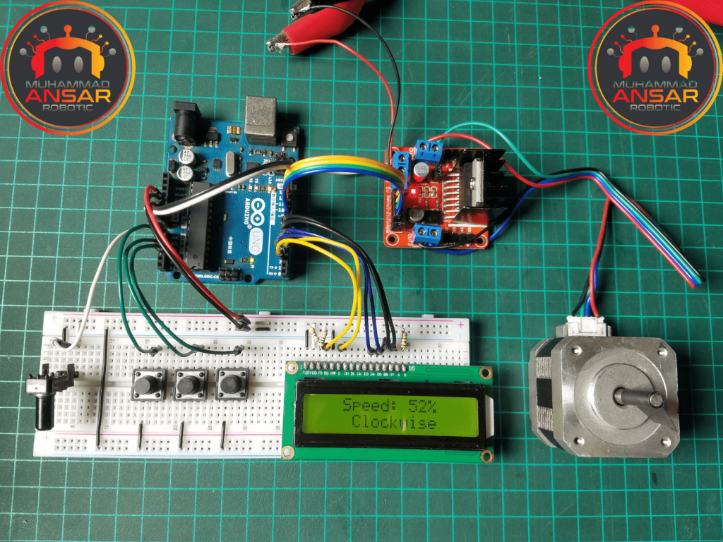
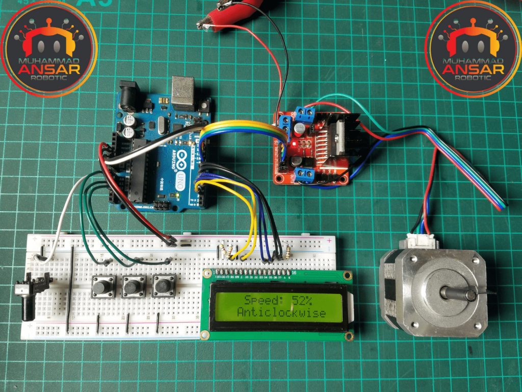
Hardware Testing
An implementation success guide for hardware testing will be supplied. It will go over how to physically connect the parts, deal with any possible problems during troubleshooting, and confirm that the stepper motor responds to UI speed changes.
Conclusion
In summary, the Stepper Motor Speed Controller project is an example of how different electrical components may be seamlessly integrated when it is executed with accuracy and creativity. The project is both a practical example of manipulating stepper motors and an instructional exercise that sheds light on the real-world uses for Arduino-based control systems. Moreover, the project’s accessibility is improved with the addition of an organized circuit diagram and extensive Arduino IDE code, which makes it a great learning tool for both experts and novices. This project captures the spirit of hands-on electronics by fusing theoretical understanding with practical execution, enabling people to explore the intriguing field of control of motors and automation.
2 responses to “Stepper Motor Speed Controller Using Arduino And L298 Motor Driver”

Thank you for your detailed and thorough introduction. The code you wrote is also very complete. I will definitely try it again if I have the chance.
Welcome


Leave a Reply