
Automatic Smart Car Barrier System Using Arduino

Introduction
The integration of smart technology into everyday operations is becoming increasingly common in our fast evolving environment. Using Arduino to construct an Automatic Smart Car Barrier System is one such application. The goal of this project is to develop a barrier system that, in a variety of locations, including parking lots or private driveways, automatically opens and closes in response to the presence of a car, improving convenience and efficiency. The HC-sr04 Ultrasonic Sensor and Mini Servo Motor SG90 are two parts that we may use with Arduino technology to build an automated and responsive barrier system.
Components Required
- VPC Cardboard 5mm
- Solderless Breadboard
- Arduino UNO
- SG90 Servo Motor
- Ultrasonic Sensor HC-SR04
- 100R Resistor x 2
- Green LED
- Red LED
- Male to Male Jumper Wires
- Hard Jumper Wire
- Battery Clip
- 9V Battery
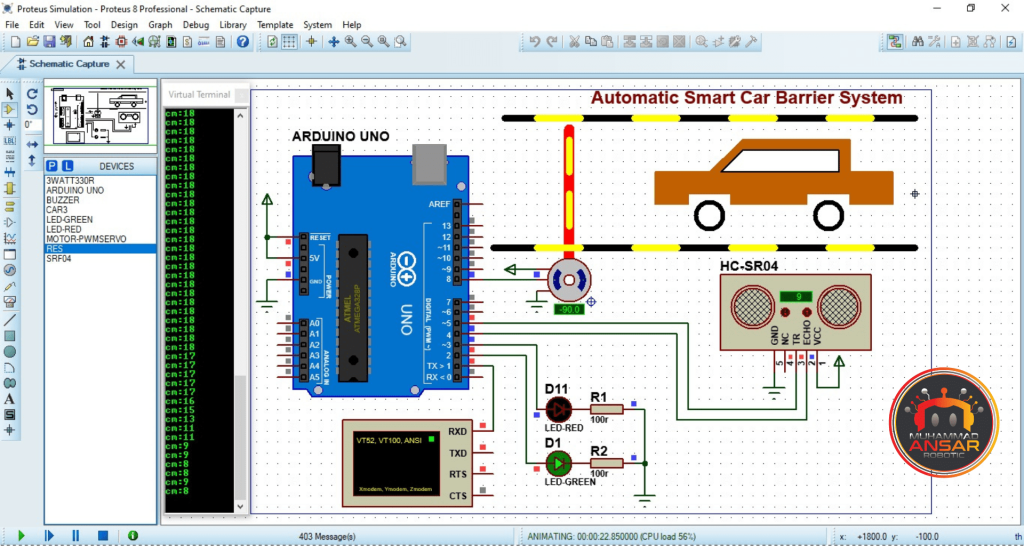
Proteus Simulation
Proteus 8 is used to model the Automatic Smart Car Barrier System project in the supplied simulation demonstration. The link in the description will take you to the simulation file. The ‘ARDUINO UNO’ board, ‘SG90’ small servo motor, an ultrasonic sensor, two LEDs (one red, one green), and a virtual terminal for tracking distance values are among the parts used in the simulation. The Arduino IDE is used to compile the Arduino code, which is in charge of managing the system. After that, the code is uploaded to the Arduino UNO board, and a copy of the generated hex file address is made. The Arduino component is setup in the Proteus simulation environment by pasting the address of the hex file. After then, the simulation starts. The virtual terminal shows the distance measurements in centimeters during the experiment. The servo motor moves the barrier from 0 to 90 degrees when the distance falls below 10 cm, signaling that an automobile is in front of the ultrasonic sensor. Concurrently, the green LED illuminates, indicating that the barrier has opened. The barrier shuts and the red LED glows after a 2000 ms delay. The distance value varies, and this cycle is repeated. The Automatic Smart Car Barrier System’s real-time functionality is aptly demonstrated by this simulation, which highlights the system’s capacity to react autonomously to the presence or absence of automobiles.
Circuit Diagram
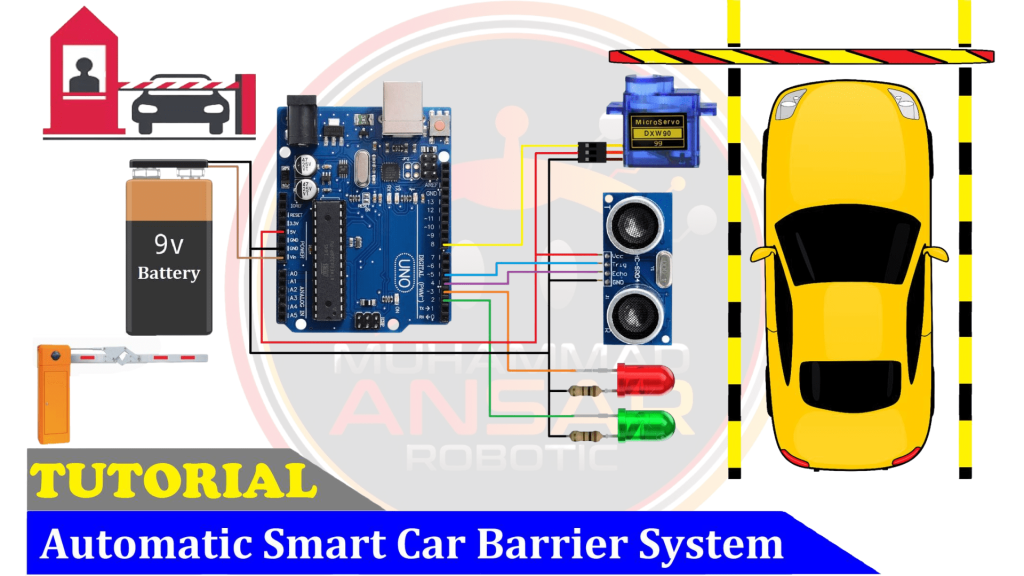
A 9-volt battery serves as the main power source for the system. The Arduino UNO serves as the circuit’s central control unit, coordinating the actions of all the circuit’s components. The circuit incorporates two LEDs, identified by their red and green hues. The negative terminals of each LEDs are linked in series with 100-ohm resistors to provide a circuit that leads to the ground. Control over the LEDs’ lighting is made possible by connecting the positive pins of the LEDs to pins 2 and 3 of the Arduino UNO. The HC-SR04 ultrasonic sensor is a crucial part of the system for identifying automobiles. It is essential in deciding when to raise and lower the barrier. The barrier is physically manipulated by use of a tiny servo motor, SG90. The Arduino UNO uses the data from the ultrasonic sensor to control the movement of the servo motor. This circuit design demonstrates the smooth integration of parts in the Automatic Smart Car Barrier System by ensuring a logical and ordered connection between the power supply, control unit, sensors, and actuators. When implementing the hardware, referring to this circuit design guarantees that the system will respond to the presence or absence of vehicles in a suitable manner.
Arduino IDE Code
#include <Servo.h>
Servo myservo;

#define G_led 2 // choose the pin for the Green Led
#define R_led 3 // choose the pin for the Red Led

#define echopin 4 // echo pin
#define trigpin 5 // Trigger pin

int cm; // Duration used to calculate distance
int degree=0, flag=0;
int set_time=2000;
long rememTime;

void setup(){ // put your setup code here, to run once
Serial.begin(9600);// initialize serial communication at 9600 bits per second:

myservo.attach(8); // declare Servo Motor as output
myservo.write(degree);

pinMode(R_led,OUTPUT); // declare Red LED as output
pinMode(G_led,OUTPUT); // declare Green LED as output

pinMode(trigpin, OUTPUT); // declare ultrasonic sensor Echo pin as input
pinMode(echopin, INPUT);  // declare ultrasonic sensor Trigger pin as Output

delay(500);
}

void loop(){
// Write a pulse to the HC-SR04 Trigger Pin
digitalWrite(trigpin, LOW);
delayMicroseconds(2);
digitalWrite(trigpin, HIGH);
delayMicroseconds(10);

// Measure the response from the HC-SR04 Echo Pin
long ultra_time = pulseIn (echopin, HIGH);
  // Determine distance from duration
  // Use 343 metres per second as speed of sound
cm =  ultra_time / 29 / 2;

Serial.print("cm:");Serial.println(cm);

if(cm<10)rememTime = millis(); // set start time

if((millis()- rememTime) > set_time){
digitalWrite(G_led, LOW); // LED Turn Off.
digitalWrite(R_led, HIGH); // LED Turn On
if(flag==1){ flag=0;
for(degree=90; degree>0; degree-=1){
myservo.write(degree);
delay(3);
  }
 }
}else{
digitalWrite(G_led, HIGH); // LED Turn On
digitalWrite(R_led, LOW); // LED Turn Off
if(flag==0){ flag=1;
for(degree=0; degree<90; degree+=1){
myservo.write(degree);
delay(3);
  }
 }
}

delay(100);
}
Explanation
To make controlling the servo motor easier, the Servo library is first included in the code. ‘myservo’ is the initialization value for the servo motor. In addition, the green and red LEDs’ respective pins 2 and 3 are initialized. The ultrasonic sensor’s trigger and echo pins are configured as 4 and 5, respectively. We introduce variables like’set_time’ for barrier open time, ‘flag’ for loop control, ‘degree’ for servo motor position, and ‘cm’ for distance. The code initializes the serial communication at a baud rate of 9600 and establishes the starting circumstances, including the servo motor at 0 degrees and the pin modes of the LEDs. The code continuously measures the distance from the ultrasonic sensor and outputs it to the serial monitor during the main loop. After then, it measures the distance to ascertain whether a car is there. The remaining time is set to the designated time for barrier opening and the flag is set to reset the timer if the distance falls below 10 cm. Based on the amount of time that has passed, the code controls when the barrier opens and closes. The barrier shuts when the remaining time approaches the designated open time, and vice versa. The flag variable makes sure that some parts of the code run just once, until the system is triggered by the next car. When the barrier is opening and closing, a for loop is used to smoothly move the servo motor between 0 and 90 degrees. With a 100 millisecond lag, the code runs continuously to guarantee real-time responsiveness. To put it briefly, the code uses the servo motor and ultrasonic sensor to intelligently coordinate the Automatic Smart Car Barrier System’s actions in response to the presence or absence of a vehicle.
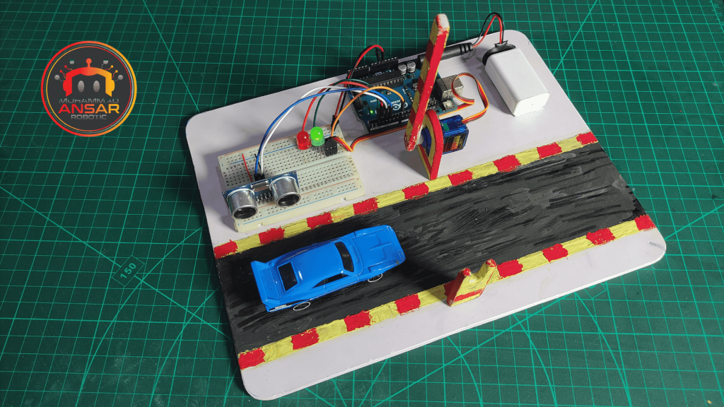
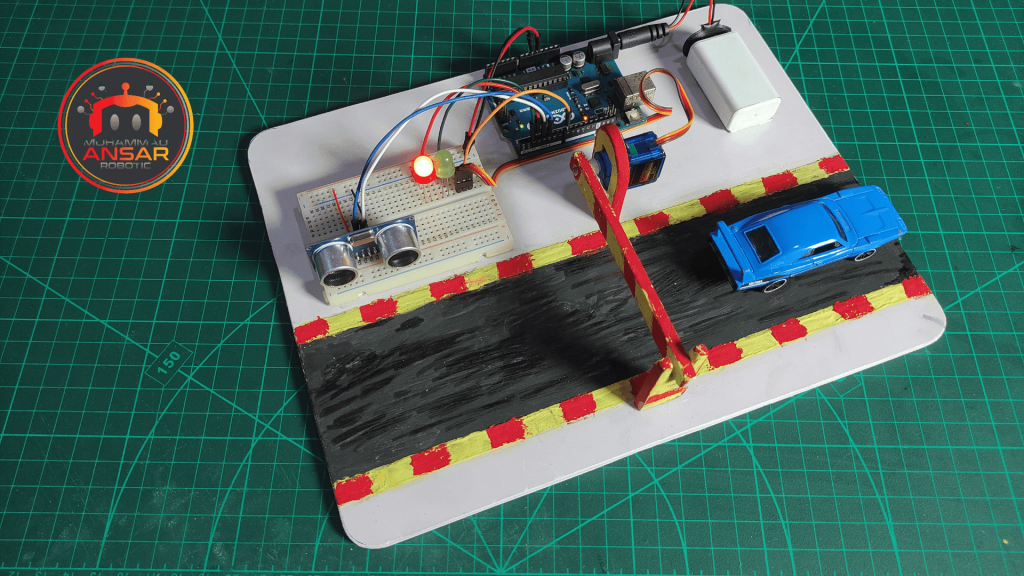
Hardware Testing
Use the 9V battery to power the system after the circuit has been completed and the code has been uploaded to the Arduino Uno. Keep an eye on how the barrier system reacts to a vehicle’s presence or absence. Make that the LEDs appropriately display the system’s state and that the servo motor moves the barrier in accordance with that indication.
Conclusion
The Automatic Smart Car Barrier System, in summary, is a useful and adaptable project that highlights the possibilities of Arduino technology. The HC-sr04 Ultrasonic Sensor and Mini Servo Motor SG90 are two parts that we may use to build an effective and automated vehicle access control system. This project advances the use of smart technology in our daily lives by providing access to a range of applications in smart parking systems and security solutions.
One response to “Automatic Smart Car Barrier System Using Arduino”

Good


Leave a Reply