
RFID based Automatic Vehicle Barrier Control

Introduction
The rapid growth of technology in today’s society has redefined our daily experiences. One such example of innovation is the RFID-based Automatic Vehicle Barrier Control project, which combines the ease of use of an Arduino-based system with the power of radio-frequency identification (RFID) technology (RFID RC522). This Smart Car Barrier System provides a practical way to manage vehicle access in a variety of settings, such as protected buildings and parking lots.
Components Required
- Drawing Board
- VPC Cardboard (5mm)
- Solderless Breadboard
- Arduino UNO
- RC522 RFID Module
- Mini Servo Motor SG90
- Traffic Light Module
- Male to Male Jumper Wires
- Hard Jumper Wire
- Battery Clip
- 9V Battery
Circuit Diagram
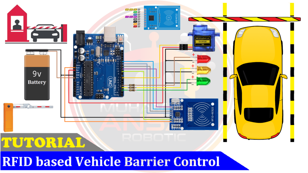
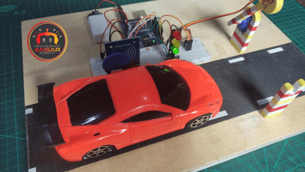
The circuit schematic overview indicates that the RFID-based Automatic Vehicle Barrier Control system will be powered by a 9-volt battery. An Arduino Uno, which acts as the project’s central processing unit, is in the center of the configuration. An RFID tag reader, the RC522, that uses the Serial Peripheral Interface (SPI) protocol is attached to the Arduino Uno. Though scanning RFID tags is the only thing covered in this video, the RC522 RFID module may be used to read and write data in the 13.56 MHz ISM band. Subsequent films might delve more into the skills of both writing and reading tags. The circuit also has three LEDs (Green, Yellow, and Red) that represent the various system statuses in addition to the RFID module. These LEDs constitute a visual signaling system when they are directly connected to the ground and have 100-ohm resistances connected in series to their positive terminals. User-friendly feedback is added by the color-coded LEDs, which offer information about the access control system’s status. A little servo motor (SG90) has been included into the circuit to operate the barrier physically. This servo motor improves the system’s overall functioning by automating the barrier’s opening and closing.
Arduino IDE Code
#include "MFRC522.h"

#define RST_PIN 9
#define SS_PIN 10

MFRC522 mfrc522(SS_PIN, RST_PIN);

byte readCard[4];
String tagID = "";

int check=0;
const int Set=3;
String Tag[Set] = {"ID1","ID2","ID3"};

#define g_led 2 // Green LED Pin
#define y_led 3 // Yellow LED Pin
#define r_led 4 // Red LED Pin

#define servo 7

void setup() {
Serial.begin(9600);// Initiating
SPI.begin(); // SPI bus
mfrc522.PCD_Init(); // MFRC522

pinMode(g_led, OUTPUT);
pinMode(y_led, OUTPUT);
pinMode(r_led, OUTPUT);

pinMode(servo, OUTPUT);
servoPulse(servo, 30);

digitalWrite(g_led, 0);
digitalWrite(y_led, 0);
digitalWrite(r_led, 1);

delay(500);
}

void loop() {//Wait until new tag is available
  while(getID()){
    Serial.println(tagID);
    check = 0;
    for (int i=0; i<Set; i++){
    if(tagID == Tag[i]){check=1;
      digitalWrite(g_led, 1);
      digitalWrite(y_led, 0);
      digitalWrite(r_led, 0);
      for(int angle=30; angle<=140; angle++){servoPulse(servo, angle);}
      delay(5000);
      digitalWrite(g_led, 0);
      digitalWrite(y_led, 1);
      digitalWrite(r_led, 0);
      delay(1000);
      for(int angle=140; angle>=30; angle--){servoPulse(servo, angle);}
      i=Set;
     }
    }

if(check==0){
  for(int x=0; x<10; x++){
digitalWrite(g_led, 0);
digitalWrite(y_led, 0);
digitalWrite(r_led, 0);
delay(500);
digitalWrite(y_led, 1);
delay(500);
  }
}

digitalWrite(g_led, 0);
digitalWrite(y_led, 0);
digitalWrite(r_led, 1);
}
delay(10);
}

//Read new tag if available
boolean getID(){// Getting ready for Reading PICCs
  if ( ! mfrc522.PICC_IsNewCardPresent()) { //If a new PICC placed to RFID reader continue
  return false;
  }
  if ( ! mfrc522.PICC_ReadCardSerial()) { //Since a PICC placed get Serial and continue
  return false;
  }
  tagID = "";
  for ( uint8_t i = 0; i < 4; i++) { // The MIFARE PICCs that we use have 4 byte UID
  //readCard[i] = mfrc522.uid.uidByte[i];
  tagID.concat(String(mfrc522.uid.uidByte[i], HEX)); // Adds the 4 bytes in a single String variable
  }
  tagID.toUpperCase();
  mfrc522.PICC_HaltA(); // Stop reading
  return true;
}

void servoPulse (int pin, int angle){
int pwm = (angle*11) + 500;      // Convert angle to microseconds
 digitalWrite(pin, HIGH);
 delayMicroseconds(pwm);
 digitalWrite(pin, LOW);
 delay(30);                   // Refresh cycle of servo
}
Explanation
The requisite header files, namely “MFRC522.h,” are first included in the code, which then initializes the reset and SS pins for the RC522 module. Next, the code creates variables for storing tag data, such as the String variable “tagID” and the variable “check.” We introduce the variable “Set” to specify how many tags the machine will be able to identify. As of right now, the example, “Set” is set to 2, meaning that two tags will be stored and recognized by the system. The servo motor and LEDs (green, yellow, and red) have pin assignments. The barrier’s opening and closing are handled by the servo motor. When all saved tags have been checked and no match is discovered, the yellow LED flashes to signal a mismatch. One method in the code, “getID,” is used to translate the 4-bit tag data into a string so that it may be compared. The “servoPulse” function modifies the angle in response to the pulse duration that is supplied, hence controlling the movement of the servo motor. Additional features like managing numerous tags, signaling a discrepancy with the yellow LED, and granting a wait before rechecking for tags are included in the code’s conclusion. Before uploading the code, the uploader is told to verify the baud rate, pick the Arduino Uno board, and choose the appropriate port.
Hardware Testing
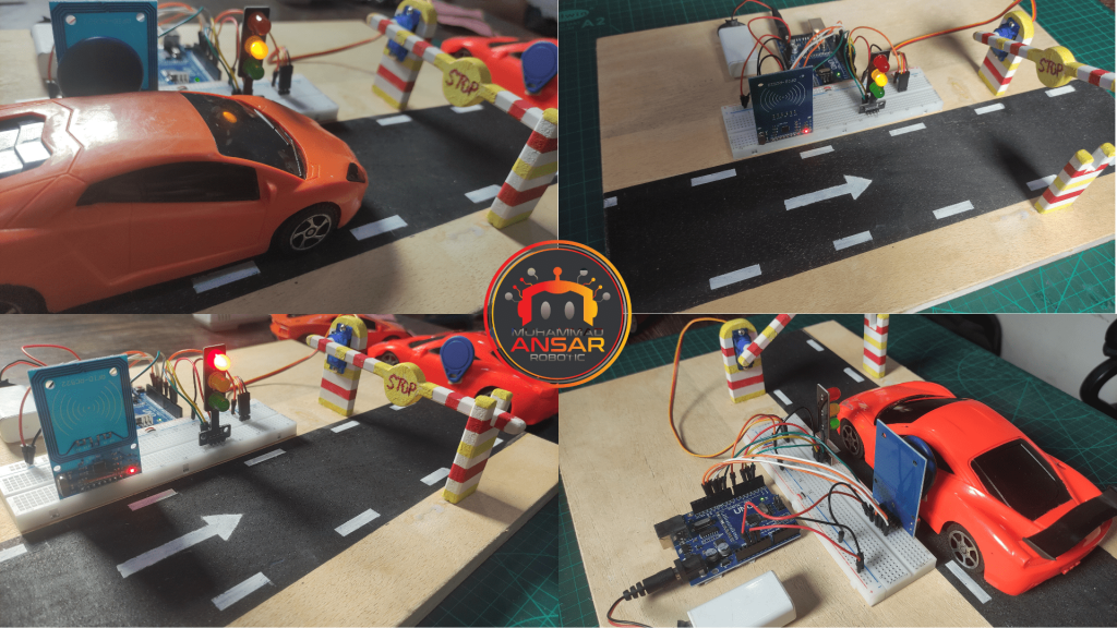
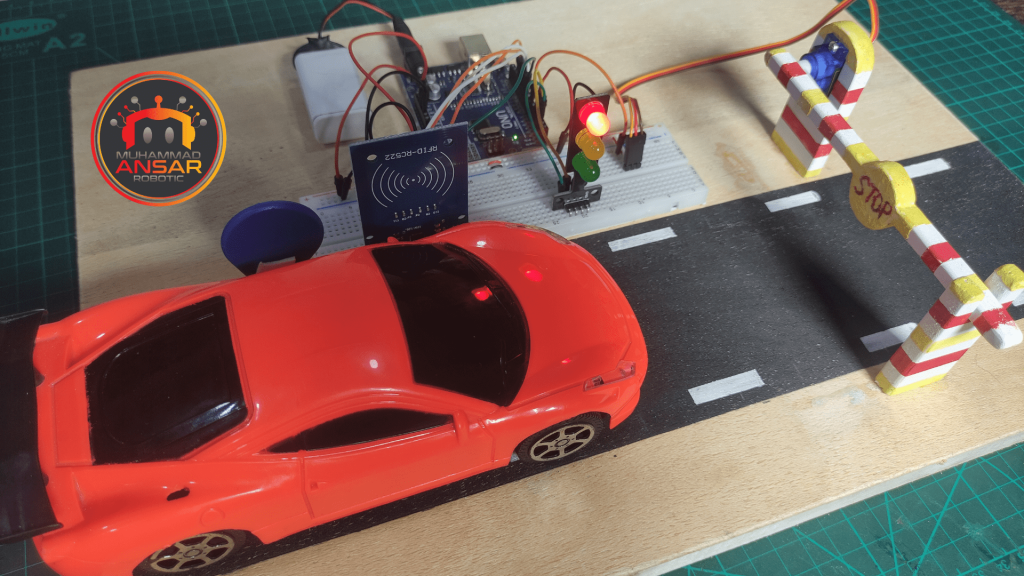
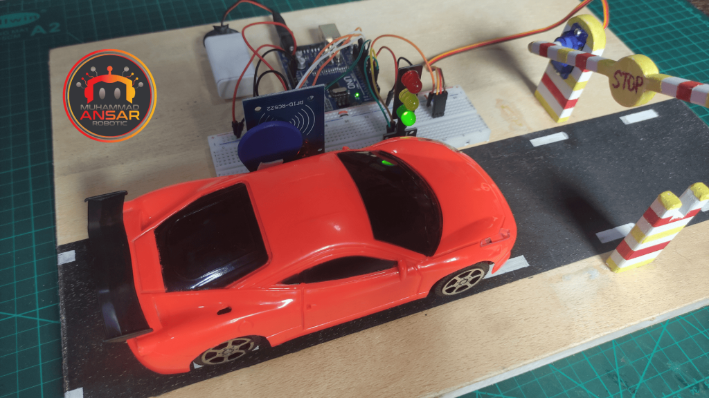
Upon completion of the circuit assembly and code upload, it is necessary to do comprehensive hardware testing. When RFID cards are added to the system, see how the barrier reacts. Make that the traffic light module appropriately indicates the access status and that the servo motor runs smoothly. In order to ensure that the system is reliable, resolve any problems that may come up during the testing process.
Conclusion
The Automatic Vehicle Barrier Control project, which uses RFID technology, offers a creative and useful way to control vehicle entry. This Smart Car Barrier System provides an adaptable and adjustable method of automatic entry control by fusing RFID technology with Arduino. Projects like these demonstrate the potential for developing clever and effective solutions in a variety of fields, from parking management to security applications, as technology continues to advance. This project has the potential to improve the effectiveness and security of access control systems with careful installation and testing.
One response to “RFID based Automatic Vehicle Barrier Control”

Can you send me the data base pleas


One thought on “RFID based Automatic Vehicle Barrier Control”
 dilshan says:
Can you send me the data base pleas
Leave a Reply