
Configure And Pair Two HC-05 Bluetooth Modules

Introduction
Because of Bluetooth technology, wireless communication between devices is now possible in modern electronics. In this project, we will explore pairing and setting two HC-05 Bluetooth modules for an Arduino-based two-way communication system. This creates opportunities for data sharing, remote control applications, and other uses. Let’s examine the parts and procedures needed to put up this fascinating project.
Components Required
- Solderless Breadboard
- Solderless Breadboard (Small)
- Arduino UNO
- Arduino Nano
- HC-05 Bluetooth Module x 2
- Mini Servo Motor SG90
- Push Button
- 10k Variable Resistor
- 100R Resistor
- Red LED
- Male Header
- Male to Male Jumper Wires
- Hard Jumper Wire
- Battery Clip x 2
- 9V Battery x 2
Circuit Diagram
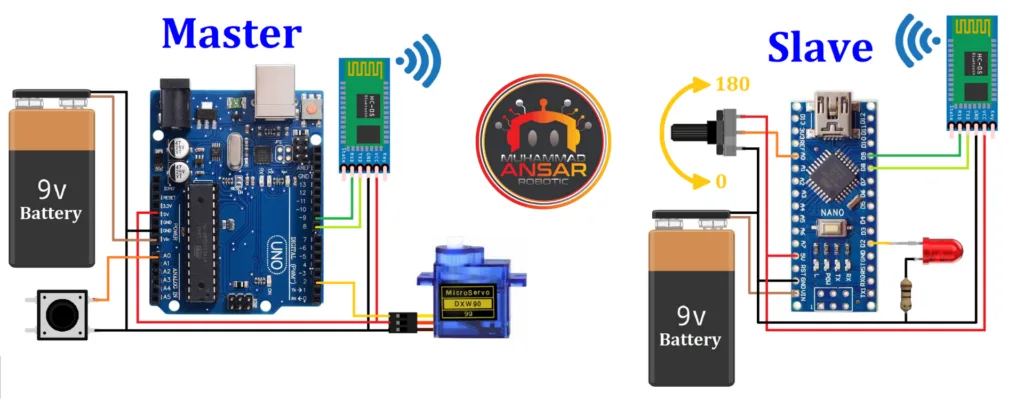
The main component of the design, as shown in the master circuit diagram, is a 9-volt battery that powers the device. The Arduino UNO microcontroller was selected due to its adaptability. Data interchange with the slave component is made possible by wireless connection facilitated by the HC-05 Bluetooth module. A tiny servo motor that is variable-controlled gives dynamic movement to the system, and a push button that is included into the design offers a tactile input. Interestingly, pins 8 and 9 are used to begin external serial communication. In this setup, a button variable is transmitted to the slave by the master, which gets a variable pertaining to the servo motor. The LED’s state is dependent on the state of the button, adding a visually engaging component to the main configuration. Similar to the master circuit, the slave circuit runs on a 9-volt battery. Nonetheless, an Arduino Nano is selected as the microcontroller in this case, providing a small yet effective answer. Analog input is provided via a 10-kilohm potentiometer, and connection with the master is facilitated using an HC-05 Bluetooth module. An LED functions as a visual indication using data from the master in conjunction with a 100-ohm resistor connected in series. Pins 8 and 9 are used to initiate external serial connection, which guarantees successful communication with the master. A variable associated with the servo motor is sent to the master in the slave setup, which adds to the total dynamic interaction.
Note
The circuit schematics for the Bluetooth master and slave, whether they use Arduino Nano or Arduino UNO microcontrollers, are customized to fit the particular setup of the selected Arduino model. When both an Arduino Nano and an Arduino UNO are used, connections are made in accordance with their own setups. In the event that there is just one Arduino available—a UNO or Nano, for example—the connections are modified appropriately to provide for flexibility in accommodating various Arduino board configurations. This method enables the Bluetooth master and slave communication system to be implemented with ease and supports users with varying microcontroller alternatives.
Pairing Bluetooth Modules
In order to achieve flawless communication between two Bluetooth modules, a methodical procedure needs to be followed. The slave module is first instructed to get its Bluetooth address. This address is essential to the next actions. Subsequently, an Arduino is connected to the master Bluetooth module, and commands are sent to setup the master module. The “AT+BIND” instruction is used to set the Bluetooth address that was acquired from the slave. When two Arduino boards are used, the master and slave connections are made, and the system is connected to a computer. Before configuring, the slave’s COM prompt is accessed, and standard commands like “AT” and “AT+UART?” are run to verify configurations. Successful data transfer requires that the master and slave have matching baud rates. “AT+ROLE?” is used to set the roles of master and slave; “AT+ADDR?” is used to acquire the slave’s address. I’ve copied this address for future reference. The COM prompts for the slave and master are opened as we go on to the master settings. The master module’s baud rate is found by experimenting with different baud rates. The “AT+UART” command is used to change the baud rate of the master module after it has been detected. “AT+ROLE=1” sets the master’s role to 1, and “AT+CMODE=0” sets the connection mode. Next, using “AT+BIND,” the slave’s Bluetooth address is connected to the master, making sure that the address’s colons are changed to commas. The enabling pins are removed from the device to test it after successful configuration. The serial monitor of the master displays data transmitted from the slave’s COM prompt, and vice versa. At last, the components are put together in accordance with the schematic, activated, and linked to a laptop. During this phase, the enable pin must get 5 volts. Bidirectional data transfer confirms that the Bluetooth modules have successfully paired, indicating that the pairing procedure is complete.

Arduino IDE Code
Slave Code
/* How to configure and pair two HC-05 Bluetooth Modules
 *               == SLAVE CODE ==
 */

#include <SoftwareSerial.h>
SoftwareSerial mySerial(8, 9); // RX, TX

#define potentiometer  A0  //10k Variable Resistor
#define ledPin 2

int state = 0;
int potValue = 0;

void setup() { // put your setup code here, to run once
 pinMode(potentiometer, INPUT);
 pinMode(ledPin, OUTPUT);
 Serial.begin(9600); //Begin serial communication with Arduino and Arduino IDE (Serial Monitor)
 mySerial.begin(9600); // Default communication rate of the Bluetooth module
 delay(100);
}

void loop() {
 if(mySerial.available() > 0){ // Checks whether data is comming from the serial port
    state = mySerial.read(); // Reads the data from the serial port
 }
 // Controlling the LED
 if (state == '1') {
  digitalWrite(ledPin, HIGH); // LED ON
  state = 0;
 }
 else if (state == '0') {
  digitalWrite(ledPin, LOW); // LED ON
  state = 0;
 }
 // Reading the potentiometer
 potValue = analogRead(potentiometer);
 int potValueMapped = map(potValue, 0, 1023, 0, 180);
 mySerial.write(potValueMapped); // Sends potValue to servo motor
 delay(300);
}
Explanation
Because the Arduino Nano does not have a separate hardware serial for Bluetooth connection, the code for the slave component starts by adding the SoftwareSerial library. Pins 8 (RX) and 9 (TX), dubbed mySerial, are used to create external serial connection since pins 0 and 1, the built-in serial, are used for code uploading. Pin A0 is linked to a 10-kilohm potentiometer, while pin 2 is set aside for an LED. To control the LED’s state and save potentiometer values, two variables are declared: “state” and “potValue.” The LED pin is set to OUTPUT mode, the potentiometer pin is set to INPUT mode, and the built-in serial and mySerial serial baud rates are initialized at 9600 within the void setup() section. After then, there is a 100 millisecond pause to provide reliable startup. The code then receives data from mySerial constantly in the void loop() portion. The’state’ variable is equal to the received data. LED control is based on the value of’state’. The LED is set to HIGH, turning it on, and’state’ is immediately reset to 0 if it is 1. In contrast, the LED is turned to LOW, turning it off, and’state’ is reset to 0 if’state’ is 0. The master push button affects this’state’ variable. The code changes the ‘potValue’ variable, reads the analog value from the potentiometer, and translates this value from 0 to 1023 to a range of 0 to 180 all at once. The mapped value is sent to the master via mySerial and saved in ‘potValueMapped’. This loop transmits potentiometer values for servo motor control and guarantees that the slave responds to changes in the master’s push button. The configuration of the slave component is finished when the code is detailed and uploaded to the Arduino Nano via the Arduino IDE.
Master Code
/* How to configure and pair two HC-05 Bluetooth Modules
*               == MASTER CODE ==
*/

#include <SoftwareSerial.h>
SoftwareSerial mySerial(8, 9); // RX, TX

#include <Servo.h>
Servo myServo;

#define button A0

int state;
int buttonState;

void setup() { // put your setup code here, to run once
 pinMode(button, INPUT_PULLUP);
 myServo.attach(2);
 Serial.begin(9600); // Begin serial communication with Arduino and Arduino IDE (Serial Monitor)
 mySerial.begin(9600); // Default communication rate of the Bluetooth module
 delay(100);
}

void loop() {
 if(mySerial.available() > 0){ // Checks whether data is comming from the serial port
    state = mySerial.read(); // Reads the data from the serial port
 Serial.println(state);
 }
 // Controlling the servo motor
 myServo.write(state);
 delay(300);

 // Reading the button
 buttonState = digitalRead(button);
 if (buttonState == LOW) {
  mySerial.write('1'); // Sends '1' to the master to turn on LED
 }else{mySerial.write('0');}
}
Explanation
The SoftwareSerial library, which is necessary to enable communication on the Arduino UNO, which shares built-in serial pins 0 and 1 for code uploading, is included in the master component’s code at the beginning. Pins 8 (RX) and 9 (TX), sometimes referred to as mySerial, are used to initiate external serial connection. To operate the servo motor, which is initialized as myServo, the Servo library is also called. It also declares two variables,’state’ and ‘buttonState,’ to control the servo motor control and button states, respectively, and allots pin A0 for the push button. Pin 2 is designated for myServo, and the button pin is in the INPUT mode within the void setup() section. In order to maintain consistency with the slave module, the built-in serial and mySerial both have their serial baud rates set to 9600. After then, there is a 100 millisecond pause to provide reliable startup. As we get to the void loop() section, the code updates the’state’ variable by continually reading data from mySerial. The position of the servo motor is then controlled by writing the’state’ value to myServo. For bi-directional communication, the potentiometer value that was previously sent by the slave module is subsequently written back to mySerial. The push button’s digital reading is preceded by a brief pause of 10 milliseconds. Based on the button’s state, conditional checks decide whether to transmit a ‘1’ or ‘0’ through mySerial.’ The ‘buttonState’ variable is changed appropriately. Through this connection, a slave side LED is controlled to produce a visual signal. When the code is finished, it is uploaded to the Arduino UNO via the Arduino IDE, allowing the master component to communicate with the slave circuit without any problems.
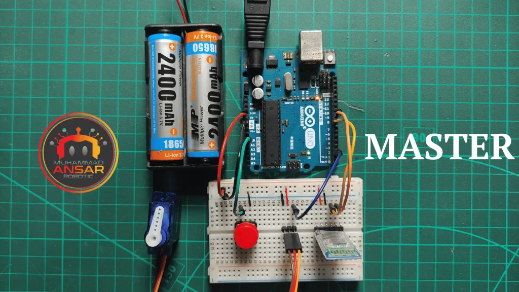
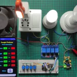
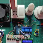
Hardware Testing
It’s time to test the hardware after wiring the circuit and uploading the code. Make sure all connections are tight before using the 9V batteries to power up the Arduino boards. Sending signals or data between the two HC-05 Bluetooth modules will allow you to test their connectivity. Make that the LED, servo motor, and other parts function as they should by checking them. Address any problems that surface during this testing phase.


Conclusion
Two HC-05 Bluetooth modules have been successfully set up and linked for two-way Arduino connection. This project is a useful and adaptable addition to your electronics projects since it offers you a plethora of options for remote control applications. Try out various parts, codes, and applications to learn more about what Bluetooth technology can do for your projects.

Leave a Reply