
Wireless Temperature And Humidity Monitoring System Using DHT-22 Sensor

Introduction
The “Wireless Temperature and Humidity Monitoring System” from MArobotics, which uses the DHT-22 sensor, is a cutting-edge solution. This project effortlessly integrates the DHT-22 sensor with wireless technology to allow for real-time temperature and humidity monitoring. MArobotics’ implementation provides a practical and effective means to wirelessly collect environmental data, making it appropriate for applications like home automation, industrial monitoring, and climate management. With an emphasis on accuracy and simplicity, this project shows how sensor technology and wireless communication may be used to improve environmental monitoring. A crucial component of many applications, ranging from industrial operations to home automation, is wireless temperature and humidity monitoring. In this project, we will investigate how to use the DHT-22 sensor and Bluetooth connection to develop a straightforward yet efficient wireless temperature and humidity monitoring system. To give real-time data wirelessly, the project makes use of widely accessible parts including an Arduino Nano, an HC-05 Bluetooth Module, and a DHT-22 sensor.
Components Required
- Solderless Breadboard
- Arduino UNO
- Arduino Nano
- HC-05 Bluetooth Module x 2
- DHT-22 Temperature and Humidity Sensor
- Male to Male Jumper Wires
- Hard Jumper Wire
- Battery Clip x 2
- 9V Battery x 2
Proteus Simulation
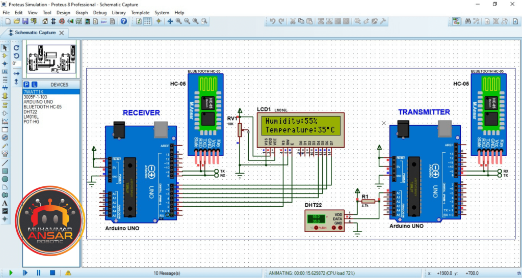
To make sure the circuit works, it is advisable to simulate it in Proteus before moving on to the hardware implementation. Before completing the actual setup, the simulation aids in locating and resolving any possible problems. Examine how the parts behave in a simulated setting to ensure the design is sound. Open the simulation file on Proteus 8. Compile the code and copy hex file address and paste in simulation file Arduino. Then, run the simulation file. We can vary the values of temperature and humidity from DHT22 sensor in the simulation. On the receiver side, in first line of the LCD displays the value of Humidity in % and in second line it displays the value of temperature in degree Celsius.
Circuit Diagram
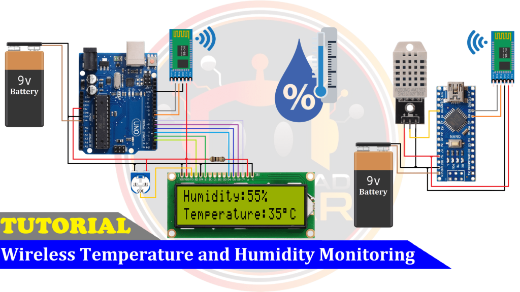
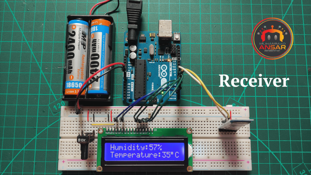
There are two circuit parts in this project. One is for transmitter and second is for the receiver. For transmitter, in the diagram below we have used Arduino Nano. A 9 volts power supply is used. A DHT22 sensor is used that is operating at 5 volts from the Arduino. A HC-05 bluetooth module is used. It also operates at 5 volts. In the receiver side circuit, an Arduino UNO is used. A 9 volts power supply is provided. A HC-05 bluetooth module is used. It also operates at 5 volts from Arduino. A 16×2 LCD is used as a display. A 10k potentiometer is used for contrast setting. Make accurate connections for smooth working.
Arduino IDE Code
Transmitter Code
#include "DHT-22.h"
#include <SoftwareSerial.h>
SoftwareSerial BT_Serial(8, 9); // RX, TX

#define DHT22_PIN A0 // what pin on the arduino is the DHT22 data line connected to
DHT22 dht(DHT22_PIN);

int temp, hum;

void setup() {
 Serial.begin(9600);
 BT_Serial.begin(9600);
 dht.begin();
 delay(2000);
}

void loop(){

dht.readHumidity();
dht.readTemperature();

hum = dht.humidity;
temp = dht.temperature_C;

BT_Serial.write("A");
BT_Serial.write(hum);
BT_Serial.write(temp);
delay(500);
}
Explanation
The included Arduino code uses a DHT22 sensor and Bluetooth connectivity to create a wireless temperature and humidity monitoring system. First, it loads the libraries required for SoftwareSerial communication and the DHT22 sensor. Digital pins 8 and 9 are used for RX and TX, respectively, to generate a SoftwareSerial object called BT_Serial. Analog pin A0 is where the DHT22 sensor’s data line is described as being linked. The setup() function initializes the DHT22 sensor, adds a 2-second delay, and initializes the software and hardware serials for Bluetooth and USB connection, respectively. The DHT22 sensor is used to continually acquire temperature and humidity data for the loop() function. The BT_Serial.write() method is then used to send these values via Bluetooth. The protocol is delivering the temperature and humidity readings first, then the letter ‘A’ as a start signal. A 500 millisecond delay is added before the following repetition. For reliable readings, it’s important to remember that the Bluetooth communication receiver must interpret the data in accordance with the established protocol.
Receiver Code
#include <LiquidCrystal.h>
LiquidCrystal lcd(2, 3, 4, 5, 6, 7);

#include <SoftwareSerial.h>
SoftwareSerial BT_Serial(8, 9); // RX, TX

int temp, hum;

byte Data[3]={'0','0','0'};

void setup() {
Serial.begin(9600);
BT_Serial.begin(9600);

lcd.begin(16,2);
lcd.setCursor(0,0);
lcd.print(" WELCOME To  My ");
lcd.setCursor(0,1);
lcd.print("YouTube  Channel");
delay(2000);
lcd.clear();
}

void loop(){

if(BT_Serial.available()>2){
   Data[0]=BT_Serial.read();
if(Data[0]=='A'){
   Data[1]=BT_Serial.read();
   Data[2]=BT_Serial.read();
}
hum = Data[1];
temp = Data[2];
Serial.print(hum);  Serial.print(" \t ");
Serial.println(temp);
}

lcd.setCursor(0,0);
lcd.print("Humidity:");
lcd.print(hum);
lcd.print("%  ");

lcd.setCursor(0,1);
lcd.print("Temperature:");
lcd.print(temp);
lcd.print((char)223); //degree symbol
lcd.print("C  ");

delay(100);
}
Explanation
The required libraries, LiquidCrystal for LCD interface and SoftwareSerial for software serial connection creation, are first included in the code. The LCD pin configuration is used to initialize the lcd object, while pins 8 (RX) and 9 (TX) are used to configure BT_Serial for Bluetooth connection. The temperature and humidity readings obtained over Bluetooth will be stored in the variables temp and hum, respectively. The received data is stored as bytes in the Data array, which is populated with default values. Serial communication is started for both the software (Bluetooth) and hardware (USB) serials in the setup() method. The LCD is set up in 16×2 size, and it displays a welcome message for two seconds before clearing. The code checks if the Bluetooth serial buffer has more than two bytes available in the main loop. If this is the case, it reads the temperature and humidity values from the next two bytes after reading the first byte (‘A’) as a start indicator. The hum and temp variables contain these values. For debugging reasons, the received data is also printed to the serial monitor. The temperature and humidity readings are then updated on the LCD and shown on different lines. For stability, a 100 millisecond delay is included. This receiver code makes the Arduino ideal for situations where real-time environmental monitoring is crucial by enabling it to wirelessly receive temperature and humidity data and display it on an LCD screen.
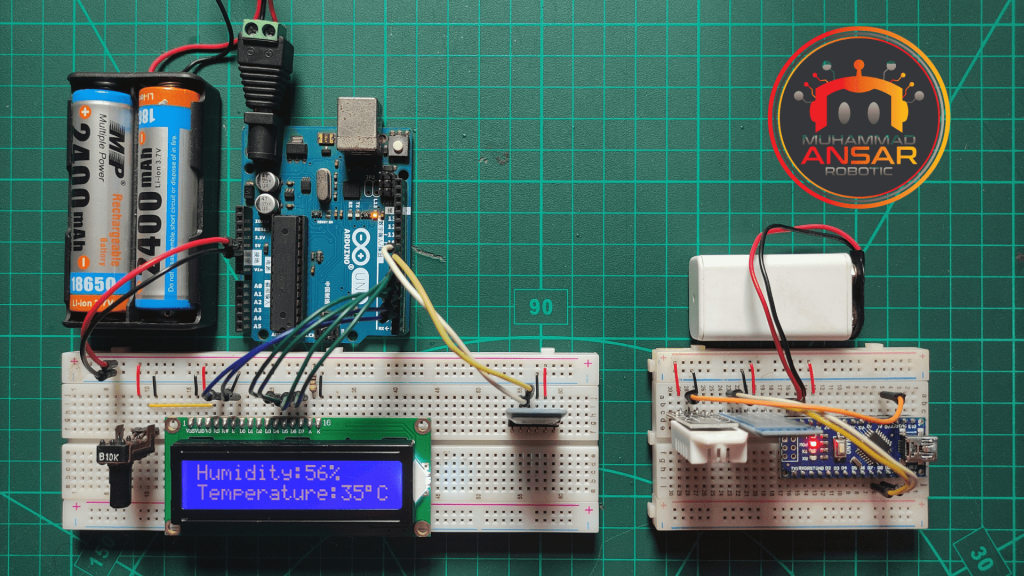
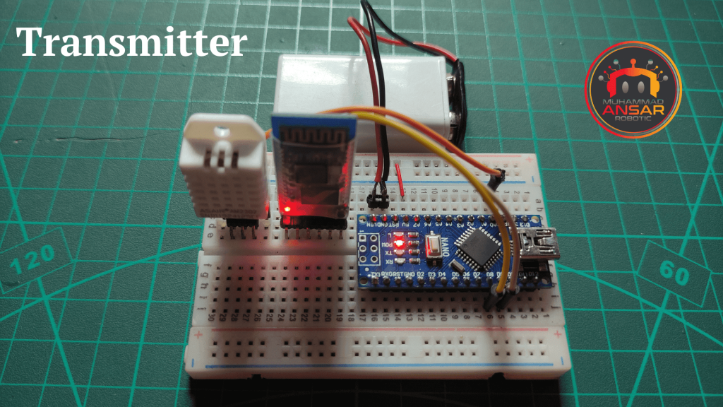
Hardware Testing
Hardware testing should be done when the circuit is put together on the breadboard and the Arduino Nano’s code has been uploaded. Verify that data is correctly sent to the receiving device via the Bluetooth module. The transmitter side has DHT22 sensor. It senses temperature and humidity. By bluetooth it is sent to the receiver side. The receiver receives the values by bluetooth and displays them on the LCD.
Conclusion
To sum up, the Arduino code that has been supplied serves as a receiver part of a wireless system for monitoring humidity and temperature. Through the use of Bluetooth connectivity and an LCD, the code is able to effectively accept data sent from a distant device. The LCD interface is easy to use and makes it possible to clearly see the temperature and humidity measurements in real time. For situations like smart home systems or industrial settings—where wireless environmental monitoring is useful—this research provides a workable and affordable alternative. This receiver code’s efficacy and simplicity make it a good starting point for developing and tailoring wireless sensor networks for a range of applications.
2 responses to “Wireless Temperature And Humidity Monitoring System Using DHT-22 Sensor”

Very nice sir 👌
I love u and your waythank you


2 thoughts on “Wireless Temperature And Humidity Monitoring System Using DHT-22 Sensor”
 Kamal saroop says:
Very nice sir 👌
I love u and your way
Leave a Reply