
4 Way Traffic Light Control Using 555 Timer And CD4017

Introduction
As essential components of urban infrastructure, traffic lights control traffic and provide safe crossings. In this project, we’ll look at how to use a CD4017 shift register and a 555 timer to build a 4-way traffic light control system. This practical project offers a useful application of circuit design by fusing electronics and programming to simulate the operation of a traffic light.
Components Required
- Solderless Breadboard x 2
- 555 Timer
- CD4017 Shift Register
- 100k Variable Resistor
- C945 NPN Transistor x 5
- 100R Resistor x 8
- 100uF Capacitor
- 1k Resistor x 5
- 10k Resistor
- Blue LED
- Red LED x 4
- Yellow LED x 4
- Green LED x 4
- 1N4148 Diode x 24
- Battery Clip
- 9V Battery
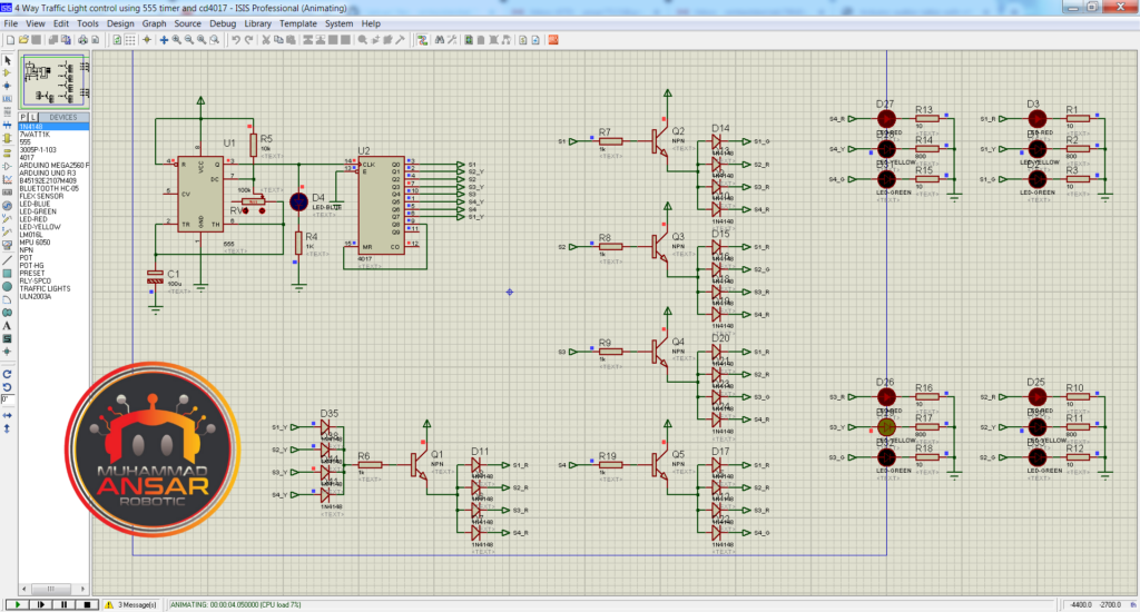
Proteus Simulation
Open Proteus simulation file on Proteus 7. Firstly, we have used a 555 timer IC for generating clock. A 10k ohm resistance is connected to its pin 7 with other end at the positive terminal. A 100k ohm variable resistance is attached with the pin 6 and 2 from pin 7. Pin 2 and 6 are connected to ground with a 100 micro farad capacitor. Pin 3 is the output pin. A LED (blue) is connected with pin 3 for indication. It is further attached to the pin 14 of 4017 IC. In 4017 IC, there are 10 outputs from Q0 to Q9. We need only 8 outputs for operating the signal. Q0, Q1, Q2, Q3, Q4, Q5, Q6, Q7 are used for this purpose. From Q8, the shift register is reset. Q8 (pin 9) is attached to the reset pin (pin 15). As this IC 4017 will get the clock, it will shift the output to the next pins. And when it will come from Q8, it will go the reset pin and will be shifted to Q0. From Q0, the output is used as an input for S1. S1 is connected with a 1k ohm resistance to the base of the npn transistor. Positive is connected to the collector pin of the transistor. Output from the emitter is given to four diodes. This is for operating 4 LEDs of different signals. At a time, one signal will be green and three signals will be red. And when output will come from Q1, yellow LED of signal 2 is operated. If yellow LED of S1, S2, S3, and S4 is operated, then 4 diodes 4148 are used and they are connected with S1_Y, S2_Y, S3_Y, and S4_Y respectively. The output of these 4 diodes is altogether connected to 1k ohm resistance, which is connected to the base of a npn transistor. The collector of this transistor is connected to positive and the output from the emitter is given to 4 diodes. The output of these 4 diodes is connected to 4 red LEDs S1_R, S2_R, S3_R, and S4_R.
When the output will come from Q0, S1 green LED will be on and red LEDs of S2, S3, and S4 will be on. When the output will come from Q1, red LEDs of all the signals will be operated and yellow LED of signal 2 will be operated. When the output will come from Q2, S2 green LED will be on and red LEDs of S1, S3, and S4 will be on. When the output will come from Q3, red LEDs of all the signals will be operated and yellow LED of signal 3 will be operated. When the output will come from Q4, S3 green LED will be on and red LEDs of S1, S2, and S4 will be on. When the output will come from Q5, red LEDs of all the signals will be operated and yellow LED of signal 4 will be operated. When the output will come from Q6, S4 green LED will be on and red LEDs of S1, S2, and S3 will be on. When the output will come from Q7, red LEDs of all the signals will be operated and yellow LED of signal 1 will be operated.
To change the time, we have used the 100k ohm potentiometer. By increasing its value, the on and off time of the clock signals is increased and the time is increased. And by decreasing the value of the resistance the time will decrease.
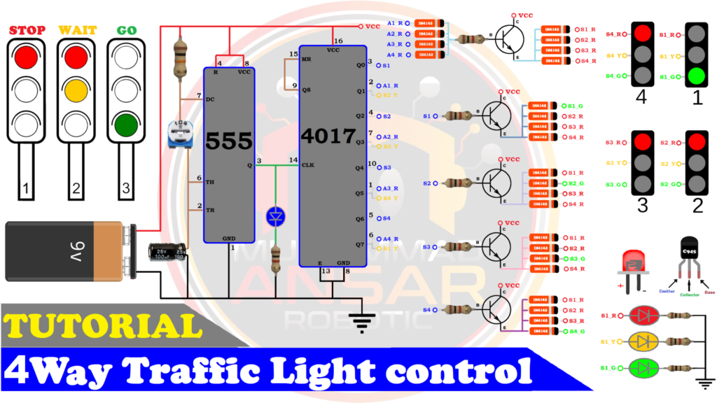
Circuit Diagram
For power source, we have used a 9 volts battery. The 555 timer IC is used to generate the clock signal. A 100k ohm potentiometer is used to increase or decrease the time. The diodes 4148 are used. We have used the npn transistor C945. Connections must be according to the following diagram for proper functioning of the system.
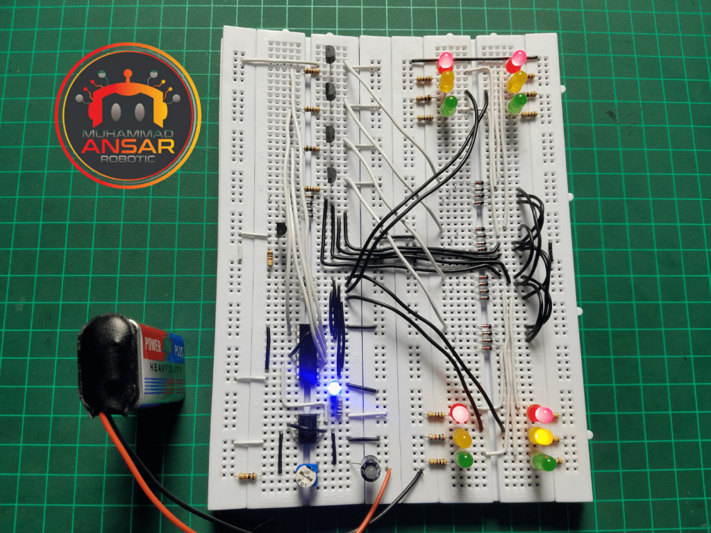
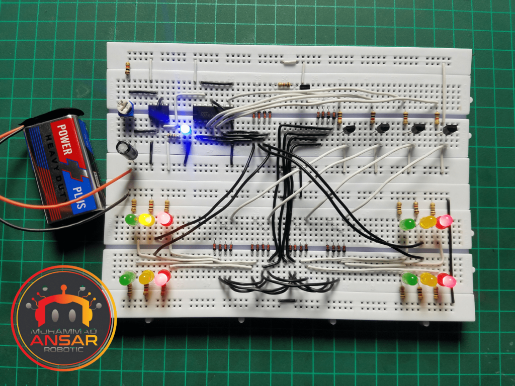
Hardware Testing
The hardware arrangement presented allows for the simulation of a four-way traffic signal controller system. It starts with a 555 timer IC creating a clock signal, which is modified by a 100k ohm variable resistor. This clock signal is then sent to a 4017 IC, which functions as a decade counter by cycling through its outputs successively. These outputs are linked to signal lights in each direction of traffic movement. Green LEDs represent the active signal direction, whilst red LEDs signify inactive directions. A yellow LED represents the transitional stage between signal changes. Each signal direction has its own set of LEDs, and the color transitions are managed by a diode-based transistor arrangement. The timing of the clock signal may be changed by modifying the resistance of the potentiometer, affecting the duration of each traffic signal phase. This extensive hardware arrangement accurately replicates the operation of a four-way traffic signal controller, which manages traffic flow at an intersection.
Conclusion
To sum up, this project offers a useful, hands-on experience in the planning and execution of a four-way traffic light management system. The 555 timer and CD4017 shift register together demonstrate the adaptability of electronic parts in building intricate circuits. You can learn a lot about troubleshooting and circuit optimization by using Proteus simulation and hardware testing. This project gives you a practical application of circuit design by simulating real-world circumstances, in addition to improving your electronics abilities.


Leave a Reply