
Tachometer With PNP and NPN Sensor Using Arduino

Introduction
A tachometer, sometimes referred to as an RPM (Revolutions Per Minute) meter, is a tool used in motorized systems to gauge how quickly a shaft or disk rotates. In this project, we’ll look at how to use an Arduino UNO and other parts to make a tachometer. PNP and NPN sensors will both constitute the foundation of the RPM meter, giving it versatility for many uses. After following this tutorial, you should have a working tachometer that can detect and show a DC motor’s rotational speed.
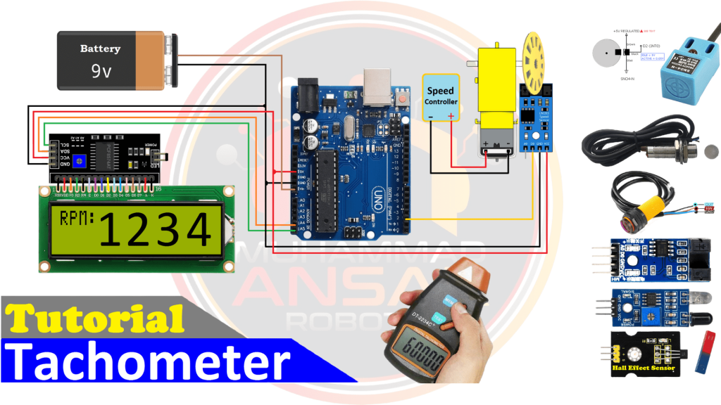
Components Required
- Arduino UNO
- 16×2 LCD Display
- I2C LCD Module
- Slot Type IR Optocoupler Sensor
- Hall Effect Sensor
- PWM Speed Controller
- DC Motor
- Magnets x 4
- Encoder Disk
- Male to Female Jumper Wires
- Battery Clip
- 9V Battery
Proteus Simulation
We start by using an Arduino UNO as the core control unit in the Proteus 8.12 simulation for the Tachometer project. After that, the configuration includes a 16×2 LCD display together with a liquid crystal I2C module for easier connection. A pulse width modulation (PWM) circuit is used to precisely control the rotational speed of the DC motor. An encoder motor is also included in the project; to track the motor’s rotations, its encoder pulse is linked to Arduino pin 2. The Arduino code must be opened and built in the Arduino IDE in order to run the simulation. After compilation, a copy of the hex file is utilized in the Proteus simulation. The compilation process is walked through with users, and emphasis is placed on how crucial it is to make sure the code and header files are in the same folder. The RPM measurement is shown on the 16×2 LCD display through simulation. An initial message is shown on the LCD for 2000 milliseconds while the motor runs, and then the RPM value is shown. The motor speed is determined by the duty cycle, which is fixed at 50%. The procedure for modifying the duty cycle is guided through for users, showing them how it impacts the motor’s speed as well as the LCD’s resolution per minute display. An overview of the encoder motor, which has a 2500 RPM, and the relationship between duty cycle modifications and the ensuing changes in motor speed and RPM are provided at the end of the simulation. A thorough comprehension of the simulation and its important parameters is provided by the explanation of the code’s setup for the PNP signal produced by the motor.
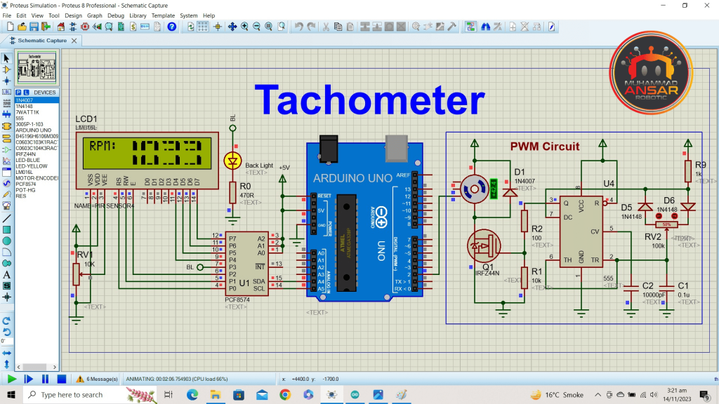
Circuit Diagram
The power supply is a 9V battery, which powers the Arduino Uno, the central control unit. An I2C module in conjunction with a 16×2 LCD guarantees a simple and clear display interface. A disk fastened to the motor produces 20 pulses with a resolution of one using the U-type Optocoupler, which is utilized to measure RPM. Because of the circuit design’s versatility, users can include various sensors with PNP or NPN designs. The code is designed to adjust appropriately, indicating the number of pulses per resolution and describing the type of sensor. In order to ensure smooth execution, the video highlights how important it is to align the code and header files in the same folder. In addition, the setup of variables such as set_pulse and max_rpm, as well as the initialization of the LCD address and sensor pin, are explained. The significance of these variables is emphasized by the fact that max_rpm sets the maximum RPM display limit and set_pulse indicates the number of pulses per resolution. All things considered, the circuit layout and its corresponding code provide a thorough approach to constructing a tachometer, providing flexibility and lucidity in RPM tracking for diverse motor setups.
Arduino IDE Code
#include "LiquidCrystal_I2C.h"
LiquidCrystal_I2C lcd(0x3f,16,2);

#define sensor_pin 2

int sensor=1; //(PNP=1 or NPN=0)here you will set whether the sensor uses NPN or PNP
int set_pulse=1; //set how many pulses in a round here
int max_rpm = 9999; //set how many RPM you want to go to here

//Configuration for the Tachometer variables
volatile unsigned long lastPulseTime;
volatile unsigned long interval = 0;
long rpm=0;

// the 8 arrays that form each segment of the custom numbers
byte bar1[8]={B11100,B11110,B11110,B11110,B11110,B11110,B11110,B11100};
byte bar2[8]={B00111,B01111,B01111,B01111,B01111,B01111,B01111,B00111};
byte bar3[8]={B11111,B11111,B00000,B00000,B00000,B00000,B11111,B11111};
byte bar4[8]={B11110,B11100,B00000,B00000,B00000,B00000,B11000,B11100};
byte bar5[8]={B01111,B00111,B00000,B00000,B00000,B00000,B00011,B00111};
byte bar6[8]={B00000,B00000,B00000,B00000,B00000,B00000,B11111,B11111};
byte bar7[8]={B00000,B00000,B00000,B00000,B00000,B00000,B00111,B01111};
byte bar8[8]={B11111,B11111,B00000,B00000,B00000,B00000,B00000,B00000};

void sensorIsr() {
  unsigned long now = micros();
  interval = now - lastPulseTime;
  if (interval > 5000){
     rpm = 61000000UL/(interval * set_pulse);
     lastPulseTime = now;
  }
}

void setup(){ // put your setup code here, to run once
pinMode(sensor_pin, INPUT);

lcd.init();// initialize the lcd
lcd.backlight();
lcd.setCursor(0,0);
lcd.print("   Welcome To   ");
lcd.setCursor(0,1);
lcd.print(" > Tachometer < ");
delay(2000); // Waiting for a while
lcd.clear();

lcd.createChar(1,bar1);
lcd.createChar(2,bar2);
lcd.createChar(3,bar3);
lcd.createChar(4,bar4);
lcd.createChar(5,bar5);
lcd.createChar(6,bar6);
lcd.createChar(7,bar7);
lcd.createChar(8,bar8);

// Digital pin 2 maps to interrupt 0
if(sensor==0)attachInterrupt(0, &sensorIsr, FALLING);
        else attachInterrupt(0, &sensorIsr, RISING);

lastPulseTime = 0;
}

void loop(){

if(rpm >= 0){//Remove the error readings of minus values
//Let's keep this RPM value under control, between 0 and 9999
rpm = constrain (rpm, 0, max_rpm);
//If the engine is not running, print 0
if((micros() - lastPulseTime) < 5e6) {rpm = rpm;}
else{rpm = 0;}
}

lcd.setCursor(0, 0);
lcd.print("RPM:");

printNumber((rpm/1000)%10, 4);
printNumber((rpm/100)%10, 7);
printNumber((rpm/10)%10, 10);
printNumber(rpm%10, 13);

delay(500);
}

void printNumber(int value, int col) {
  if (value == 0) {
    custom0(col);
  } if (value == 1) {
    custom1(col);
  } if (value == 2) {
    custom2(col);
  } if (value == 3) {
    custom3(col);
  } if (value == 4) {
    custom4(col);
  } if (value == 5) {
    custom5(col);
  } if (value == 6) {
    custom6(col);
  } if (value == 7) {
    custom7(col);
  } if (value == 8) {
    custom8(col);
  } if (value == 9) {
    custom9(col);
  }
}


void custom0(int col){ // uses segments to build the number 0
  lcd.setCursor(col, 0);
  lcd.write(2);
  lcd.write(8);
  lcd.write(1);
  lcd.setCursor(col, 1);
  lcd.write(2);
  lcd.write(6);
  lcd.write(1);
}

void custom1(int col){
  lcd.setCursor(col,0);
  lcd.write(32);
  lcd.write(32);
  lcd.write(1);
  lcd.setCursor(col,1);
  lcd.write(32);
  lcd.write(32);
  lcd.write(1);
}

void custom2(int col){
  lcd.setCursor(col,0);
  lcd.write(5);
  lcd.write(3);
  lcd.write(1);
  lcd.setCursor(col, 1);
  lcd.write(2);
  lcd.write(6);
  lcd.write(6);
}

void custom3(int col){
  lcd.setCursor(col,0);
  lcd.write(5);
  lcd.write(3);
  lcd.write(1);
  lcd.setCursor(col, 1);
  lcd.write(7);
  lcd.write(6);
  lcd.write(1);
}

void custom4(int col){
  lcd.setCursor(col,0);
  lcd.write(2);
  lcd.write(6);
  lcd.write(1);
  lcd.setCursor(col, 1);
  lcd.write(32);
  lcd.write(32);
  lcd.write(1);
}

void custom5(int col){
  lcd.setCursor(col,0);
  lcd.write(2);
  lcd.write(3);
  lcd.write(4);
  lcd.setCursor(col, 1);
  lcd.write(7);
  lcd.write(6);
  lcd.write(1);
}

void custom6(int col){
  lcd.setCursor(col,0);
  lcd.write(2);
  lcd.write(3);
  lcd.write(4);
  lcd.setCursor(col, 1);
  lcd.write(2);
  lcd.write(6);
  lcd.write(1);
}

void custom7(int col){
  lcd.setCursor(col,0);
  lcd.write(2);
  lcd.write(8);
  lcd.write(1);
  lcd.setCursor(col, 1);
  lcd.write(32);
  lcd.write(32);
  lcd.write(1);
}

void custom8(int col){
  lcd.setCursor(col, 0);
  lcd.write(2);
  lcd.write(3);
  lcd.write(1);
  lcd.setCursor(col, 1);
  lcd.write(2);
  lcd.write(6);
  lcd.write(1);
}

void custom9(int col){
  lcd.setCursor(col, 0);
  lcd.write(2);
  lcd.write(3);
  lcd.write(1);
  lcd.setCursor(col, 1);
  lcd.write(7);
  lcd.write(6);
  lcd.write(1);
}
Explanation
The code starts by creating the LCD object with its address and size and adding the libraries required for the LiquidCrystal_I2C display. For the purpose of displaying numerical digits on the LCD, many bespoke characters are made. The sensor pin, the kind of sensor (PNP or NPN), the number of pulses per revolution, and the maximum RPM to be shown are the next important factors to be described. After presenting a welcome greeting and initializing the LCD, the code configures the custom characters for subsequent usage. The interval between successive pulses from the encoder is measured by the sensorIsr() function, which acts as the interrupt service routine. Depending on the type of sensor used, the setup() method links the interrupt to the rising or falling edge and sets up the sensor pin as an input. The RPM is continually updated and shown on the LCD using the loop() method. To avoid absurd numbers, the RPM value is limited between 0 and the maximum RPM that the user has chosen. The digits 0 through 9 are represented by bespoke character functions, while the printNumber() function is used to show each RPM digit on the LCD. In general, the code uses interrupts to precisely measure the intervals between pulses from the encoder and converts this data into RPM values that are shown on the LCD. The Tachometer allows for the real-time adjustment and observation of the motor’s duty cycle, which is represented by the RPM. The customized characters improve the LCD’s visual depiction of the RPM.
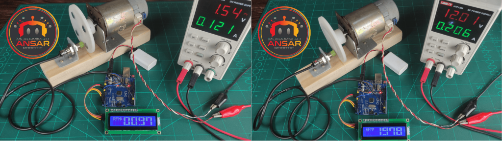
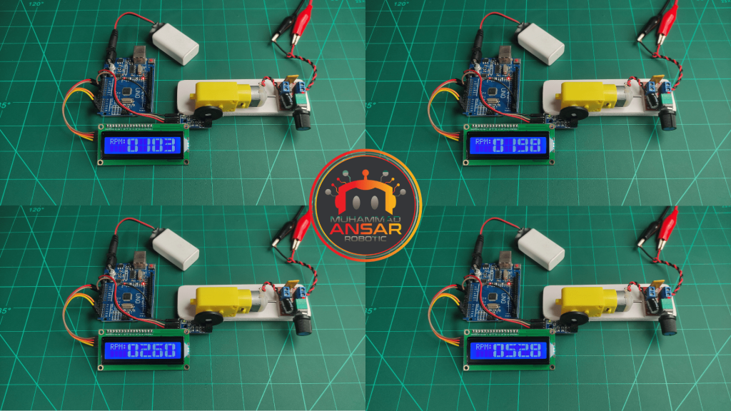
Hardware Testing
An important change to the Tachometer project’s hardware testing phase involved switching to an NPN sensor configuration and setting the sensor variable in the code to zero. Four magnets were added to the disc that was utilized with the motor to improve it; four pulses per resolution. The code was modified as a result of this change, and the variable “set_pulse” was set to 4. The code was uploaded to the Arduino Uno successfully after these hardware modifications. During this stage of hardware testing, it was confirmed that the redesigned components would integrate seamlessly and that the code would be flexible enough to accommodate various sensor kinds and pulse configurations.
Conclusion
This tachometer project effectively blends hardware elements with Arduino programming to produce a flexible RPM meter that can precisely gauge a DC motor’s revolutions per minute when fitted with an encoder. The functionality and user interface are improved by the incorporation of a 16×2 LCD display, PWM speed control, and an IR optocoupler sensor. The use of interrupts in the code guarantees accurate RPM computations, and the use of bespoke characters enhances the display’s visual clarity. In addition to offering a workable way to keep track of motor speed, this project also acts as a learning tool for anybody interested in learning more about sensor integration, interrupt management, and creating unique characters for Arduino projects.
2 responses to “Tachometer With PNP and NPN Sensor Using Arduino”

Great post! You have made exactly what I am trying to make as a first project. I have everything I need except I would like to measure very low rpms. I have a disc with 100 gaps to help with the slower speed. I would like to measure the rpm down to the 100ths ie 1.36rpm. Could you assist me with where I would change the code to do this I am very very new to Arduino. Any help would be greatly appreciated.
Please change the code at the line below:
LiquidCrystal_I2C lcd(0x3f,16,2);
to
LiquidCrystal_I2C lcd(0x27,16,2);for the LCD display to be functional correctly.
Thanks


2 thoughts on “Tachometer With PNP and NPN Sensor Using Arduino”
 Lenny says:
Great post! You have made exactly what I am trying to make as a first project. I have everything I need except I would like to measure very low rpms. I have a disc with 100 gaps to help with the slower speed. I would like to measure the rpm down to the 100ths ie 1.36rpm. Could you assist me with where I would change the code to do this I am very very new to Arduino. Any help would be greatly appreciated.
Please change the code at the line below:
LiquidCrystal_I2C lcd(0x3f,16,2);
to
LiquidCrystal_I2C lcd(0x27,16,2);for the LCD display to be functional correctly.
Thanks
Leave a Reply