
Traffic Light Signal Using 555 Timer And CD4017
Introduction
Traffic management systems are essential for controlling car flow and guaranteeing pedestrian safety in metropolitan settings. The goal of this project is to build a basic yet functional traffic light control system utilizing easily accessible electrical parts, such as the CD4017 shift register and 555 timer. The CD4017 functions as a decade counter to cycle through the traffic light phases, while the 555 timer is used to provide the required timing pulses. This blog article will walk you through the necessary parts, the circuit schematic, hardware testing, Proteus simulation, and finish with insights into the real-world use of the project.
Components Required
- Solderless Breadboard
- 555 Timer
- CD4017 Shift Register
- 100k Variable Resistor
- 100R Resistor x 3
- 100uF Capacitor x 2
- 1k Resistor
- 10k Resistor
- Blue LED
- Red LED
- Yellow LED
- Green LED
- 4007 Diode
- 4148 Diode x 11
- Battery Clip
- 9V Battery
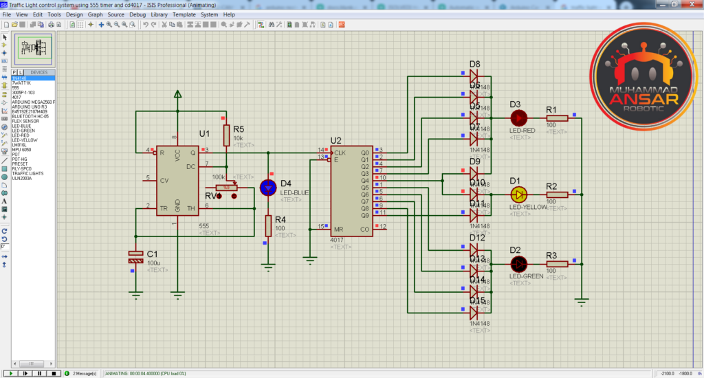
Proteus Simulation
Open Proteus simulation file on Proteus 7. Firstly, we have used a 555 timer IC for generating clock. A 10k ohm resistance is connected to its pin 7 with other end at the positive terminal. A 100k ohm variable resistance is attached with the pin 6 and 2 from pin 7. Pin 2 and 6 are connected to ground with a 100 micro farad capacitor. Pin 3 is the output pin. A LED (blue) is connected with pin 3 for indication. It is further attached to the pin 14 of 4017 IC. In 4017 IC, there are 10 outputs from Q0 to Q9. The outputs Q0, Q1, Q2, and Q3 are connected to 4 diodes 4148 respectively. Th output of these 4 diodes (D5,D6,D7,D8) is collectively connected to red LED whose other terminal is connected to ground in series with a 100ohm resistance. The output from Q4 is connected to inputs of two diodes D9 and D10. The output of D9 is connected to the output of D7. The outputs Q5, Q6, Q7, and Q8 are connected to 4 diodes (D12 to D15), whose outputs are connected to the green LED respectively. Other terminal of green LED is connected to ground in series with a 100ohm resistance. The output Q9 is connected to diode D11. The outputs of diodes D10 and D11 are collectively connected to yellow LED. Other terminal of yellow LED is connected to ground in series with a 100ohm resistance. To change the time, we have used the 100k ohm potentiometer. By increasing its value, the on and off time of the clock signals is increased and the time is increased. And by decreasing the value of the resistance the time will decrease.
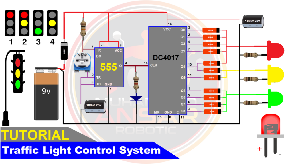
Circuit Diagram
For power source, we have used a 9 volts battery. The 555 timer IC is used to generate the clock signal. A 100k ohm potentiometer is used to increase or decrease the time. The 11 diodes 4148 are used. Three LEDs red, yellow, and green are used. The negative terminals are connected in series with a 100ohm resistance each to the ground. Connections must be according to the following diagram for proper functioning of the system.
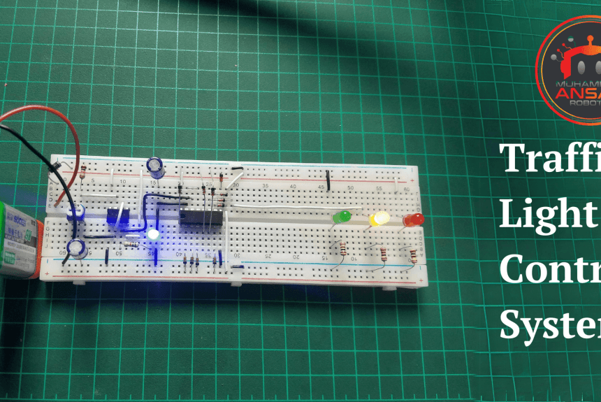
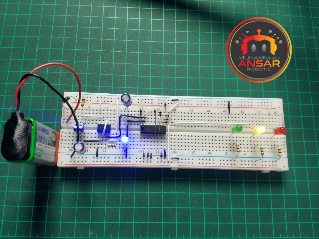
Hardware Testing
The circuit is connected on breadboard. The hardware arrangement includes a 555 timer configured in astable mode to create clock pulses that drive a CD4017 decade counter. The clock signal from the 555 timer advances the counter’s output, progressively activating different LED outputs attached to the CD4017’s Q0 to Q9 outputs. Red, green, and yellow LEDs are used, and diode logic ensures that only one LED illuminates at a time dependent on the CD4017 output. A 100k potentiometer allows you to alter the clock frequency, which controls the pace of the LED chasing effect. A 100Ω current-limiting resistor protects each LED, while a 9V battery drives the circuit, resulting in a compact and adaptable sequential LED chaser system.
Conclusion
To sum up, this project on traffic light control system shows how basic electronic components may be used to solve practical problems. The adaptability of these devices in constructing a dependable and effective traffic management system is demonstrated by the combination of the CD4017 shift register and 555 timer. Hands-on experience with electronics and microcontroller interfacing is provided by the project through hardware testing and the Proteus simulation. This project may be improved even further by aspiring electronics enthusiasts by adding features like pedestrian crossings or synchronization with other traffic signals. The information obtained from this initiative promotes research into the fields of automation and control and provides a strong basis for increasingly sophisticated traffic management systems.


Leave a Reply