
Automatic Stairs Light Control With Arduino
Introduction
Greetings from the realm of automated smart homes! We’ll walk you through the process of utilizing Arduino to create an Automatic Stairs Light Control system in this project. This creative fix improves both safety and energy savings by making sure your steps are well-lit whenever someone approaches. With the “Automatic Stairs Light Control” leveraging Arduino Nano, MArobotics provides an amazing solution for stairway illumination. This idea attempts to improve security as well as comfort by automatically activating stair lights based on motion sensing. By combining Arduino Nano, motion sensors, and LED lights, MArobotics’ solution guarantees that staircases are well-lit while people are present, encouraging safer navigation in low-light situations. This unique system provides a practical and energy-efficient solution for staircase lighting, exhibiting the smooth integration of Arduino technology for home automation and safety improvement.
Components Required
- Veroboard
- 12V 5Pin Relay x 12
- C945 NPN Transistor x 12
- PC817 Optocoupler x 12
- Arduino Nano
- Ultrasonic Sensor HC-SR04 x 2
- 4007 Diode x 13
- 1K Resistor x 24
- 10K Resistor x 12
- Green LED x 12
- Jumper Wire
- 12V LED Strip Lights
- Green Wire Connectors
- Female to Female Jumper Wires
- 12V Power Supply
Circuit Diagram
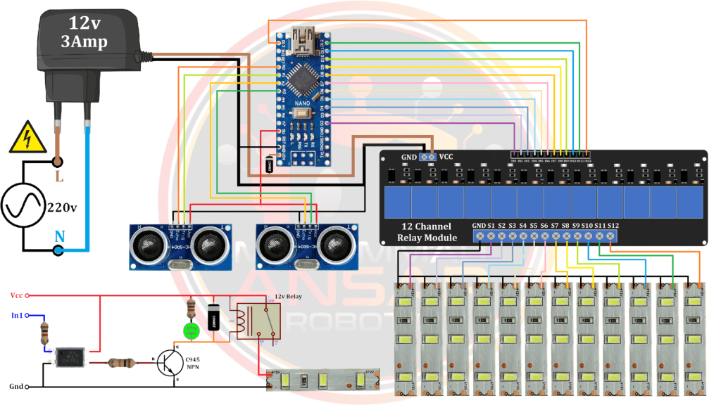
A 220-volt supply serves as the system’s main power source. A 12-volt, 2-amp power adapter is used to scale down the power supply. The numerous electronic components in the circuit depend on this lower voltage to function. The system’s tiny and potent microcontroller, the Arduino Nano, serves as its central processing unit. Twelve relays, each in charge of regulating the on/off status of a single LED strip, are connected to the Arduino. In order to effectively control the power supply to the LED strips, the relays function as switches. Relay module circuit is used to enable the connection between the Arduino and the relays. In order to fit the 12 relays utilized, this circuit, which is intended to operate high-voltage devices using a microcontroller, is duplicated 12 times. Every relay has a common terminal that is not directly linked to the positive terminal, especially when a high-voltage (220 volt) load is being handled. This guarantees the system’s overall safety and optimal operation. Two HC-SR04 ultrasonic sensors are used for people detection. Two sensors are placed strategically, one at the start of the steps and the other at the finish of the stairway. After processing the distance readings from these sensors, the Arduino sets a preset setpoint that controls when to turn on the LEDs. The LEDs light up the steps step by step as people go up or down, producing a visually beautiful and useful lighting sequence. By keeping the LEDs on for a user-specified amount of time, safety and energy efficiency are improved. Following the same progressive procedure, the LEDs gradually switch off after the specified stay time.
Relay
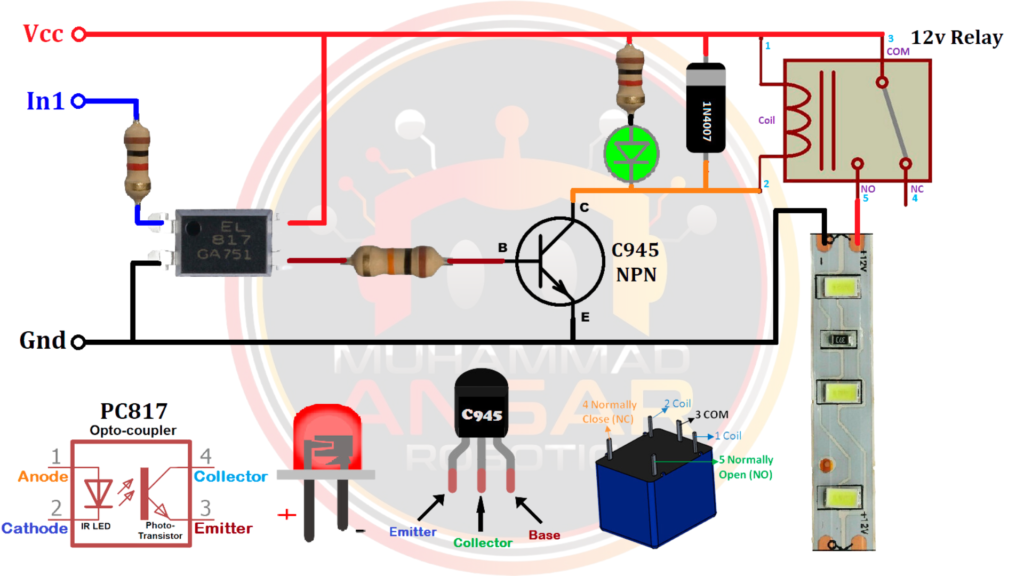
A 1-kilohm resistor, which acts as the connecting point for the incoming pulse from the Arduino, is at the center of the circuit. This resistor is essential for controlling how much current passes through the circuit. An optocoupler transistor is used after the resistor. By separating the lower-voltage Arduino electronics from the higher-voltage portions, this part ensures electrical safety and guards against possible harm. In order to enhance the regulation of current flow, a 10-kilohm resistor is positioned precisely in the circuit. Together with the optocoupler, this resistor preserves the signal’s integrity. The NPN transistor C945, a crucial component of the circuit, comes next. By functioning as a switch, this transistor makes it easier to turn on the LED and relay parts. It’s important to remember that different NPN transistors might be used in their place depending on availability and requirements. The inclusion of an LED and a 1-kilohm resistor allows for a visual indication of the circuit’s state. When the relay is activated, this LED turns on, providing a visual cue that the relay is working. The circuit uses a 4007 diode to guard against voltage spikes and guarantee that all of the parts operate as intended.
Arduino IDE Code
int set_dis = 8;    // Set distance for human read
int set_step = 12;   // Set step for Stairs Limt
int set_shift = 500; // Set shifting time for step to step MilliSecond
int set_timer = 20;   // Set on stay time for light on Second

#define e_s1 A0 //echo pin
#define t_s1 A1 //Trigger pin

#define e_s2 A2 //echo pin
#define t_s2 A3 //Trigger pin

long dis_a=0,dis_b=0;
int flag1=0, flag2=0;
int i=0;
int Second = 0;
word MilliSecond = 0;
bool timerStart = false;

int OutPins[] = {2, 3, 4, 5, 6, 7, 8, 9, 10, 11, 12, 13};


//**********************ultra_read****************************
void ultra_read(int pin_t,int pin_e,long &ultra_time){
long time;
digitalWrite(pin_t,LOW);
delayMicroseconds(2);
digitalWrite(pin_t,HIGH);
delayMicroseconds(10);
time=pulseIn (pin_e,HIGH);
ultra_time =  time / 29 / 2;
}


void setup(){
Serial.begin(9600);// initialize serial communication at 9600 bits per second:

for (i=0; i<set_step; i++) {
    pinMode(OutPins [i], OUTPUT);
}

pinMode(e_s1,INPUT);
pinMode(t_s1,OUTPUT);

pinMode(e_s2,INPUT);
pinMode(t_s2,OUTPUT);

 noInterrupts();         // disable all interrupts
 TCCR1A = 0;             // set entire TCCR1A register to 0  //set timer1 interrupt at 1kHz  // 1 ms
 TCCR1B = 0;             // same for TCCR1B
 TCNT1  = 0;             // set timer count for 1khz increments
 OCR1A = 1999;           // = (16*10^6) / (1000*8) - 1
 //had to use 16 bit timer1 for this bc 1999>255, but could switch to timers 0 or 2 with larger prescaler
 // turn on CTC mode
 TCCR1B |= (1 << WGM12); // Set CS11 bit for 8 prescaler
 TCCR1B |= (1 << CS11);  // enable timer compare interrupt
 TIMSK1 |= (1 << OCIE1A);
 interrupts();           // enable

delay(1000); // Waiting for a while
}


void loop(){
data();

if(Second==0){
if(flag1==1){ flag1=0; timerStart = false;
delay(set_shift);
for(i=set_step-1; i>-1; i--){
digitalWrite(OutPins [i], LOW);
data();
out1();
delay(set_shift);
  }
 }
}

if(Second==0){
if(flag2==1){ flag2=0; timerStart = false;
delay(set_shift);
for(i=0; i<set_step; i++){
digitalWrite(OutPins [i], LOW);
data();
out2();
delay(set_shift);
  }
 }
}

}


void data(){
ultra_read(t_s1,e_s1,dis_b);
ultra_read(t_s2,e_s2,dis_a);

Serial.print("da:");Serial.println(dis_a);
Serial.print("db:");Serial.println(dis_b);
Serial.print("time:");Serial.println(Second);

if(dis_a<set_dis){
Second = set_timer;
delay(set_shift);
if(flag1==0 && flag2==0){ flag1=1;
for(i=set_step-1; i>-1; i--){
digitalWrite(OutPins [i], HIGH);
delay(set_shift);
}
timerStart = true;
}
}

if(dis_b<set_dis){
Second = set_timer;
delay(set_shift);
if(flag1==0 && flag2==0){ flag2=1;
for(i=0; i<set_step; i++){
digitalWrite(OutPins [i], HIGH);
delay(set_shift);
}
timerStart = true;
  }
 }
}

void out1(){
if(flag1==1 || flag2==1){i=0;}
}

void out2(){
if(flag1==1 || flag2==1){i=set_step-1;}
}


ISR(TIMER1_COMPA_vect){
if(timerStart == true){MilliSecond++;
    if(MilliSecond >= 1000){MilliSecond = 0;
       Second--;
    }
  }
}
Explanation
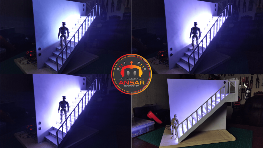
The Automatic Stairs Light Control system may be easily implemented with the help of the Arduino code that is given. Important factors like the number of steps in the staircase, the distance threshold for human detection, and the timing of step transitions and light duration are all determined during the configuration process. For example, a 20-second light stay period and a 6cm detection distance have been set for narrow steps. Because of the code’s flexibility, users may modify these parameters to suit their own staircase’s proportions and style. After setup, the Arduino IDE is used to upload the code to an Arduino Nano or Uno. This stage guarantees that the microcontroller is configured to carry out the designated lighting sequence in response to the presence of a person. The Arduino IDE’s “Done uploading” notification verifies that the upload was successful. The system is prepared for a hardware demonstration now that the code is in place. When someone approaches the stairs, the lights begin to turn on in a certain order and stay on for the predetermined amount of time before gradually going off. In addition to improving energy economy, this design offers staircase settings a thoughtful and adaptable lighting solution.
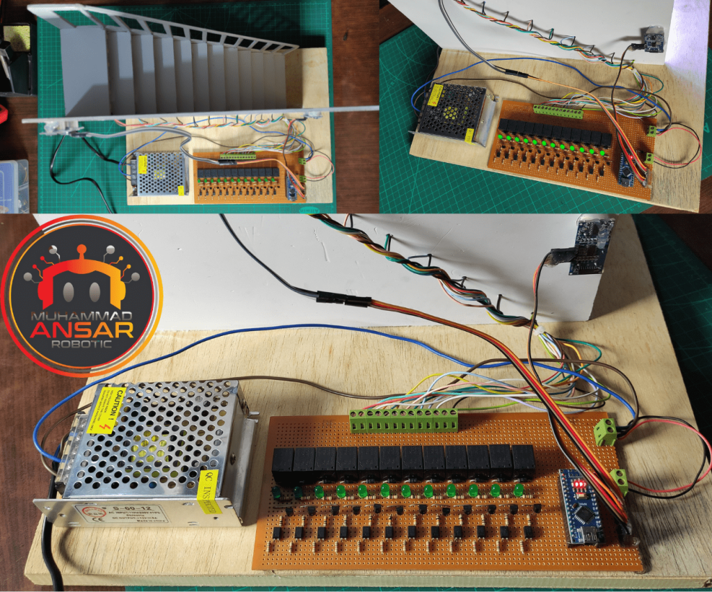
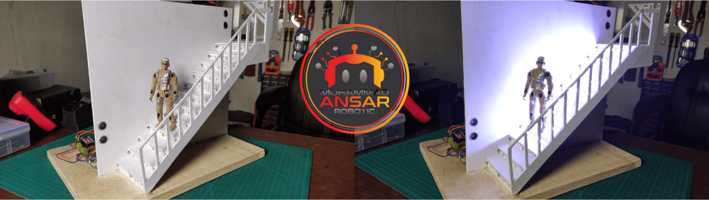
Hardware Testing
In order to include lights that have a 220 volt voltage rating into the Automatic Stairs Light Control system, the voltage must first be supplied to make the connection. In this context, the neutral line is quite important. This specific configuration makes use of 12-volt LED strips. Consequently, 12 volts should be the power supply setting for these LED strips. This guarantees that the LEDs in the system are operating properly.
Conclusion
This project ensures that lights are only turned on when necessary, which not only gives your house a little automation touch but also improves energy efficiency. Please feel free to expand and modify this project to meet your needs. Savor the secure and clever stairway lights you have!
2 responses to “Automatic Stairs Light Control With Arduino”

Sir please give me block diagram of automatic stair light project
Sorry bro block diagram is not available


2 thoughts on “Automatic Stairs Light Control With Arduino”
 Shaikh kaif says:
Sir please give me block diagram of automatic stair light project
Leave a Reply