
WiFi Based Robot With Android Application Control

Introduction
Developing a WiFi-based robot with Android application control is an intriguing endeavor that combines hardware and software skills in the field of robotics and do-it-yourself projects. In order to build a flexible robot that can be controlled by an Android application created specifically for it using MIT App Inventor, a number of components must be integrated. The Arduino NodeMcu, DC gear motors, the L298 motor driver, and a number of other electrical parts that support the robot’s operation are the main parts of this project.
Components Required
- VPC Cardboard (5mm)
- Solderless Breadboard (MB102)
- DC Gear Motor x 4
- Arduino NodeMcu
- BD139 NPN Transistor
- 1k Resistor x 3
- 100R Resistor x 2
- White LED x 2
- Red LED x 2
- L298 Motor Driver
- 4Pcs Smart Robot Car Tyers Wheels
- Male to Male Jumper Wires
- Male to Female Jumper Wires
- On/Off Switch
- 18650 Battery Holder – 2 Cell
- 18650 Battery Cell 3.7V x 2
Circuit Diagram
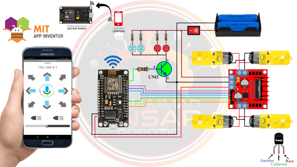
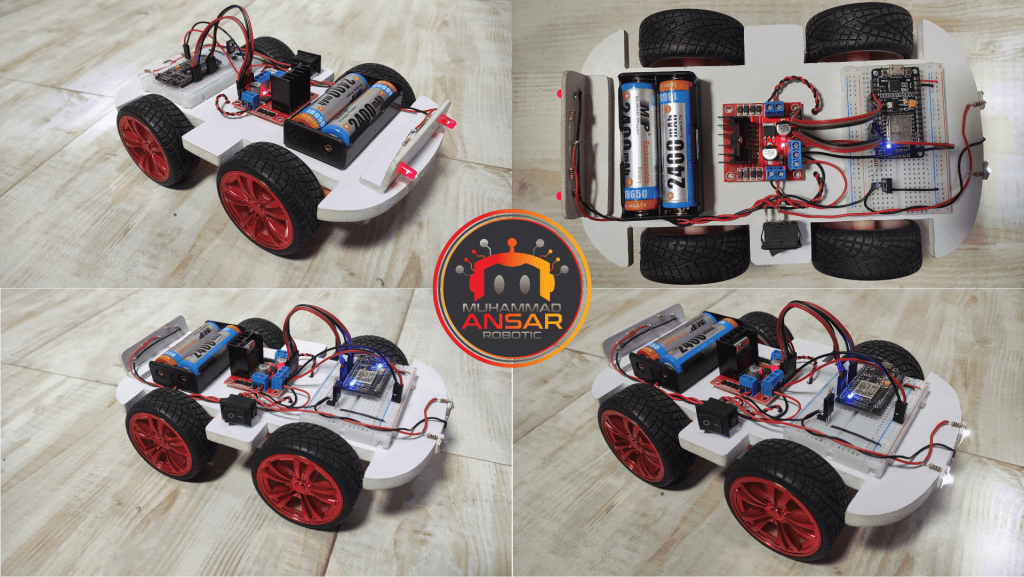
For power source, we have used two cells of 3.7 volts that together makes 7.4 volts. The negative of the source is directly connected to the circuit. A switch is used in series with the positive terminal of source to turn it on or off. Arduino Nodemcu Wifi Module is used. At its D0 pin, a C945 npn transistor is attached to control the LEDs. You can use any npn transistor. Its biasing resistance is 1 kilo ohm. 4 LEDs are operated using npn transistor. Two LEDs are red for back light and two LEDs are white for front light. 1k resistance is connected in series to each LED light. A L298 motor driver, which has two H-bridge is used by which it can move two motors clockwise and anti clockwise separately. At OUT1 and OUT2, the motors of right side are attached. At OUT3 and OUT4, the motors of left side are attached. To control the left side motors, pins D6, D7, D8 of Nodemcu are used. To control the right side motors, pins D2, D3, D4 of Nodemcu are used. At Vcc of this motor driver, 7.4 volts is input and Gnd pin is attached to the ground of the source. From motor driver, 5 volts are taken and are provided to Vin of the Nodemcu. The Nodemcu module is used in Access Point mode in which it will generate a hotspot. Mobile is connected to this hotspot.
Robot Body Design
Print this design on A4 sheet and cut it on 5mm Acrylic Sheet or Foam Board.

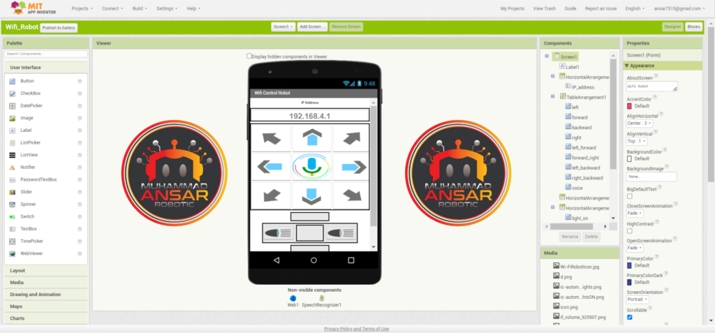
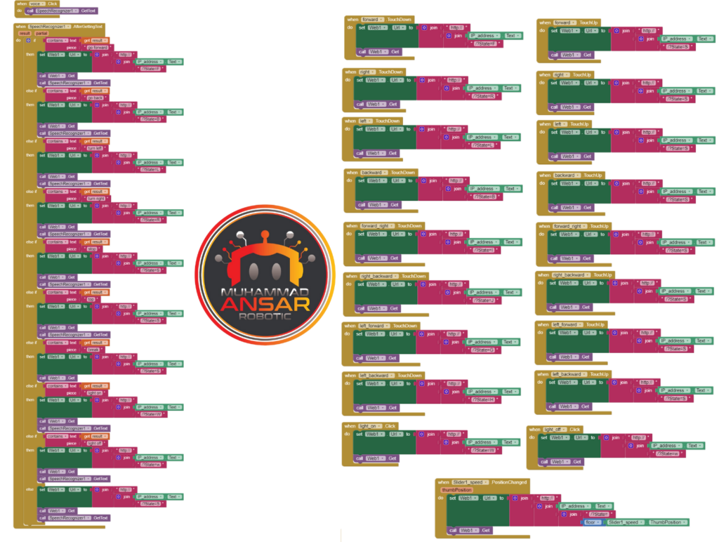
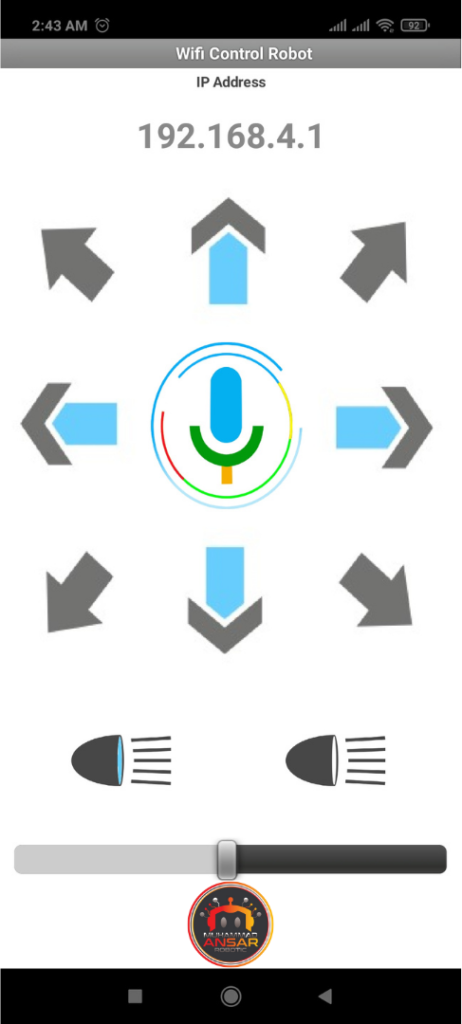
MIT App Inventor
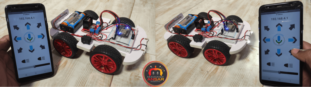
In the app, Buttons with arrows are given to move the robot. A voice command button is also given. The bullet shape buttons are for turning the LEDs on/off. At the bottom, a slider is given to control its speed. If the command is wrong, the robot will remain stopped. You can change the name, background or graphics of the application by clicking that element.
Arduino IDE Code
/* https://arduino.esp8266.com/stable/package_esp8266com_index.json
 * ESP8266 as Web Server using WiFi Access Point (AP) mode
 * Connect to AP "Robot Wifi", password = "87654321"
 */

#include <ESP8266WiFi.h>
#include <WiFiClient.h>
#include <ESP8266WebServer.h>

//SSID and Password to your ESP Access Point
const char* ssid = "Robot Wifi";
const char* password = "87654321";

#define ENA   4     // Enable/speed motors Right    GPIO4(D2)
#define IN_1  0     // L298N in1 motors Right       GPIO0(D3)
#define IN_2  2     // L298N in2 motors Right       GPIO2(D4)
#define IN_3  12    // L298N in3 motors Left        GPIO12(D6)
#define IN_4  13    // L298N in4 motors Left        GPIO13(D7)
#define ENB   15    // Enable/speed motors Left     GPIO15(D8)

#define Light  16 // Light  GPIO16(D0)

String command;             //String to store app command state.
int speedCar = 150; // 0 to 255
int speed_low = 60;

ESP8266WebServer server(80);

void setup() {

  Serial.begin(115200);

 pinMode(ENA, OUTPUT);
 pinMode(IN_1, OUTPUT);
 pinMode(IN_2, OUTPUT);
 pinMode(IN_3, OUTPUT);
 pinMode(IN_4, OUTPUT);
 pinMode(ENB, OUTPUT);

 pinMode(Light, OUTPUT);


// Connecting WiFi

  WiFi.mode(WIFI_AP);           //Only Access point
  WiFi.softAP(ssid, password);  //Start HOTspot removing password will disable security

  IPAddress myIP = WiFi.softAPIP();
  Serial.print("AP IP address: ");
  Serial.println(myIP);

 // Starting WEB-server
     server.on ( "/", HTTP_handleRoot );
     server.onNotFound ( HTTP_handleRoot );
     server.begin();
}

void loop() {
    server.handleClient();

      command = server.arg("State");
           if (command == "F") goForword();
      else if (command == "B") goBack();
      else if (command == "L") goLeft();
      else if (command == "R") goRight();
      else if (command == "I") goForwordRight();
      else if (command == "G") goForwordLeft();
      else if (command == "J") goBackRight();
      else if (command == "H") goBackLeft();
      else if (command == "W")digitalWrite(Light, HIGH); // light is on
      else if (command == "w")digitalWrite(Light, LOW);  // light is off
      else if (command == "0") speedCar = 100;
      else if (command == "1") speedCar = 120;
      else if (command == "2") speedCar = 140;
      else if (command == "3") speedCar = 160;
      else if (command == "4") speedCar = 180;
      else if (command == "5") speedCar = 200;
      else if (command == "6") speedCar = 215;
      else if (command == "7") speedCar = 230;
      else if (command == "8") speedCar = 240;
      else if (command == "9") speedCar = 255;
      else if (command == "S") stopRobot();
}

void HTTP_handleRoot(void) {

if( server.hasArg("State") ){
       Serial.println(server.arg("State"));
  }
  server.send ( 200, "text/html", "" );
  delay(1);
}

void goForword(){

      digitalWrite(IN_1, HIGH);
      digitalWrite(IN_2, LOW);
      analogWrite(ENA, speedCar);

      digitalWrite(IN_3, LOW);
      digitalWrite(IN_4, HIGH);
      analogWrite(ENB, speedCar);
  }

void goBack(){

      digitalWrite(IN_1, LOW);
      digitalWrite(IN_2, HIGH);
      analogWrite(ENA, speedCar);

      digitalWrite(IN_3, HIGH);
      digitalWrite(IN_4, LOW);
      analogWrite(ENB, speedCar);
  }

void goRight(){

      digitalWrite(IN_1, LOW);
      digitalWrite(IN_2, HIGH);
      analogWrite(ENA, speedCar);

      digitalWrite(IN_3, LOW);
      digitalWrite(IN_4, HIGH);
      analogWrite(ENB, speedCar);
  }

void goLeft(){

      digitalWrite(IN_1, HIGH);
      digitalWrite(IN_2, LOW);
      analogWrite(ENA, speedCar);

      digitalWrite(IN_3, HIGH);
      digitalWrite(IN_4, LOW);
      analogWrite(ENB, speedCar);
  }

void goForwordRight(){

      digitalWrite(IN_1, HIGH);
      digitalWrite(IN_2, LOW);
      analogWrite(ENA, speedCar-speed_low);

      digitalWrite(IN_3, LOW);
      digitalWrite(IN_4, HIGH);
      analogWrite(ENB, speedCar);
   }

void goForwordLeft(){

      digitalWrite(IN_1, HIGH);
      digitalWrite(IN_2, LOW);
      analogWrite(ENA, speedCar);

      digitalWrite(IN_3, LOW);
      digitalWrite(IN_4, HIGH);
      analogWrite(ENB, speedCar-speed_low);
  }

void goBackRight(){

      digitalWrite(IN_1, LOW);
      digitalWrite(IN_2, HIGH);
      analogWrite(ENA, speedCar-speed_low);

      digitalWrite(IN_3, HIGH);
      digitalWrite(IN_4, LOW);
      analogWrite(ENB, speedCar);
  }

void goBackLeft(){

      digitalWrite(IN_1, LOW);
      digitalWrite(IN_2, HIGH);
      analogWrite(ENA, speedCar);

      digitalWrite(IN_3, HIGH);
      digitalWrite(IN_4, LOW);
      analogWrite(ENB, speedCar-speed_low);
  }

void stopRobot(){

      digitalWrite(IN_1, LOW);
      digitalWrite(IN_2, LOW);
      analogWrite(ENA, speedCar);

      digitalWrite(IN_3, LOW);
      digitalWrite(IN_4, LOW);
      analogWrite(ENB, speedCar);
 }
Explanation
Using an L298N motor driver and an ESP8266 module configured as a web server in access point (AP) mode, this Arduino code operates a robot with motors. The ESP8266 creates a “Robot Wifi” Wi-Fi access point with the password “87654321.” The web server is set up on port 80 and IP address 192.168.4.1. The L298N module’s connection to the ESP8266 GPIO pins defines the motor control pins. On GPIO16 (D0), a light pin is also defined. The code contains routines to control the motor speed with the L298N driver and handle different movement instructions (e.g., “F” for forward, “B” for backward, “L” for left, “R” for right, etc.). The light may be turned on or off with the “W” and “w” commands, respectively. The robot may be controlled by the instructions “0” through “9,” with “S” halting it. The “State” parameter from the URL is parsed by the server in order to process HTTP requests. The motor control functions are activated in accordance with the received command, which determines the speed. An HTML page that is empty is returned by the server. The loop updates the robot’s status in response to incoming client requests, processing them continually. Through a web browser or a bespoke application, the code offers a straightforward interface for controlling the robot’s movement and lighting remotely.
HTTP_handleRoot: This function handles incoming HTTP requests and prints the value of the “State” argument if it exists, then sends an HTTP response with a status code of 200 and an empty HTML body.goForward: It sets the motor configuration to make the robot move forward at a specified speed, with one motor rotating clockwise and the other counterclockwise.goBack: This function configures the motors to make the robot move backward at a specified speed, with motor rotations opposite to the “goForward” function.goRight: It sets the motor configuration to make the robot turn right by stopping the left motor and running the right motor forward at the specified speed.goLeft: This function makes the robot turn left by stopping the right motor and running the left motor forward at the specified speed.goForwardRight: It adjusts motor speeds to make the robot move forward while turning slightly to the right, achieved by reducing the speed of the left motor relative to the right one.goForwardLeft: This function similarly adjusts motor speeds to make the robot move forward while turning slightly to the left, achieved by reducing the speed of the right motor relative to the left one.goBackRight: It configures the motors to make the robot move backward while turning slightly to the right, achieved by reducing the speed of the left motor relative to the right one.goBackLeft: This function similarly configures the motors to make the robot move backward while turning slightly to the left, achieved by reducing the speed of the right motor relative to the left one.stopRobot: It stops the robot’s movement by setting both motor configurations to a stopped state with no rotation.
Hardware Testing
Conclusion
To sum up, this project effectively illustrates how to build an Android application with MIT App Inventor that controls a WiFi-based robot. The robot creates a wireless connection and lets people control its motions and turn on a light by using the ESP8266 module as a web server in access point mode. By integrating MIT App Inventor, the Android application creation process is made simpler and offers a user-friendly interface for users to instruct the robot. This project demonstrates the smooth integration of hardware and software and provides enthusiasts with an approachable platform to investigate the potential of remote-controlled robots using easily accessible parts and approachable programming tools.
2 responses to “WiFi Based Robot With Android Application Control”

not getting MIT App inventor code file
please send


Leave a Reply