
Arduino Based Hand Gesture Control Robot

Introduction
Innovative ideas combined with state-of-the-art technology have opened up exciting new possibilities in the field of robotics. An example of a project that bridges the Arduino’s flexibility with natural hand gesture control is the “Arduino-based Hand Gesture Control Robot.” Imagine being able to control a robot with just your hand movements—a smooth fusion of technology and human communication. We’ll walk you through the steps of building your own Hand Gesture Control Robot with Arduino and a few other necessary parts in this blog article.
Components Required
Hand Control
- Solderless Breadboard
- Arduino Nano
- MPU6050 Accelerometer
- HC-05 Bluetooth Master Module
- Velcro Tape
- On/Off Switch
- Male to Male Jumper Wires
- Hard Jumper Wire
- Battery Clip
- 9V Battery
Robot
- VPC Cardboard 5mm
- Arduino UNO
- DC Gear Motor x 4
- L298 Motor Driver
- HC-05 Bluetooth Slave Module
- 4Pcs Smart Robot Car Tyers Wheels
- Male to Female Jumper Wires
- Nuts and Bolts (M2 x 50)
- On/Off Switch
- 18650 Battery Holder – 2 Cell
- 18650 Battery Cell 3.7V x 2
Circuit Diagram
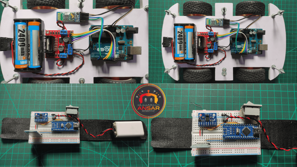
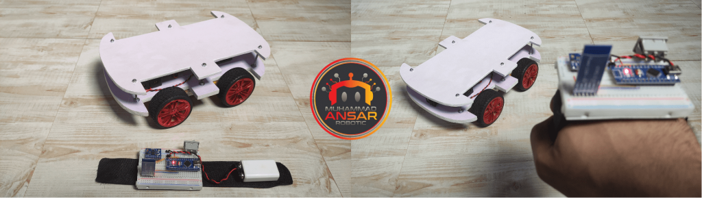
A 9-volt battery powers the transmitter circuit, and an on/off switch is positioned in the positive line to provide easy power management. An Arduino Nano is incorporated into the circuit to function as the system’s brain. Using the A4 and A5 pins, an MPU6050 servo motor sensor is linked to the Arduino Nano via the I2C protocol. Furthermore, a Bluetooth module—more precisely, the HC-05—is employed. To initiate communication, the two Bluetooth modules are set up as Master and Slave, respectively. The hand gesture controller and the robot are connected seamlessly by means of two modules, one used on the transmitter side and the other on the reception side. Let’s go on to the robot circuit. Two 3.7-volt batteries connected in series provide power, resulting in a 7.4-volt total voltage. On the positive line is a power on/off switch. An Arduino UNO forms the basis of the robot’s circuitry, while the DC gear motors are managed by an L298 motor driver. Two H-bridges on the L298 motor driver allow it to operate two DC motors in both clockwise and counterclockwise directions. The L298 driver’s Out1, Out2, Out3, and Out 4 pins are connected to motors. Pin 5 of the Arduino UNO connects to the L298’s enable B pin, while pins 6, and 7 are responsible for controlling the motors on the left side. Pins 6 and 7 are connected to the L298’s In3 and In4 to control the left-side motor’s movement. Similarly, the Arduino UNO’s pins 8 and 9 regulate the right-side motor, while pin 10 is used to activate A. Lastly, a Bluetooth module (HC-05) is included into the circuit to provide a communication link with the transmitter. The foundation of the hand gesture-controlled robot is this extensive configuration, which opens the door to natural and engaging robotic control.

Robot Body Design
Print this design on A4 sheet and cut it on 5mm Acrylic Sheet or Foam Board.

Arduino IDE Code
Hand Control Code
#include <SoftwareSerial.h>
SoftwareSerial BT_Serial(2, 3); // RX, TX

#include <Wire.h> // I2C communication library

const int MPU = 0x68; // I2C address of the MPU6050 accelerometer
int16_t AcX, AcY, AcZ;

int flag=0;

void setup () {// put your setup code here, to run once

Serial.begin(9600); // start serial communication at 9600bps
BT_Serial.begin(9600);

// Initialize interface to the MPU6050
Wire.begin();
Wire.beginTransmission(MPU);
Wire.write(0x6B);
Wire.write(0);
Wire.endTransmission(true);

delay(500);
}

void loop () {
Read_accelerometer(); // Read MPU6050 accelerometer

if(AcX<60  && flag==0){flag=1; BT_Serial.write('f');}
if(AcX>130 && flag==0){flag=1; BT_Serial.write('b');}

if(AcY<60  && flag==0){flag=1; BT_Serial.write('l'); }
if(AcY>130 && flag==0){flag=1; BT_Serial.write('r');}

if((AcX>70)&&(AcX<120)&&(AcY>70)&&(AcY<120)&&(flag==1)){flag=0;
BT_Serial.write('s');
}

delay(100);
}

void Read_accelerometer(){
      // Read the accelerometer data
Wire.beginTransmission(MPU);
Wire.write(0x3B); // Start with register 0x3B (ACCEL_XOUT_H)
Wire.endTransmission(false);
Wire.requestFrom(MPU, 6, true); // Read 6 registers total, each axis value is stored in 2 registers

AcX = Wire.read() << 8 | Wire.read(); // X-axis value
AcY = Wire.read() << 8 | Wire.read(); // Y-axis value
AcZ = Wire.read() << 8 | Wire.read(); // Z-axis value

AcX = map(AcX, -17000, 17000, 0, 180);
AcY = map(AcY, -17000, 17000, 0, 180);
AcZ = map(AcZ, -17000, 17000, 0, 180);

Serial.print(AcX);
Serial.print("\t");
Serial.print(AcY);
Serial.print("\t");
Serial.println(AcZ);
}
Explanation
Our Arduino-based Hand Gesture Control Robot project would not be possible without the hand gesture controller’s code. First, we start external serial connection by designating pins 2 and 3 for the BT_Serial using the ‘SoftwareSerial’ library. Furthermore, in order to enable connection with the MPU6050 servo motor sensor, the ‘Wire’ library is called. The address of the sensor is given, and the variables x, y, and z are initialized along with a ‘flag’ variable. The baud rates for BT_Serial and plain serial are both set to 9600 in the’setup()’ method, and ‘Wire’ is used to initialize the MPU6050. The ‘loop()’ method is where the robot moves by using hand gestures to decide its motions while the accelerometer values are updated continually. Forward, backward, left, and right motions are determined by the values of x and y, with a’stop’ command applied when x and y are in the middle range. After uploading the code to the Arduino Nano, the hand gesture controller can wirelessly understand and send commands.
Robot Code
#include <SoftwareSerial.h>
SoftwareSerial BT_Serial(2, 3); // RX, TX

#define enA 10//Enable1 L298 Pin enA
#define in1 9 //Motor1  L298 Pin in1
#define in2 8 //Motor1  L298 Pin in1
#define in3 7 //Motor2  L298 Pin in1
#define in4 6 //Motor2  L298 Pin in1
#define enB 5 //Enable2 L298 Pin enB

char bt_data; // variable to receive data from the serial port
int Speed = 150; //Write The Duty Cycle 0 to 255 Enable Pins for Motor Speed

void setup() { // put your setup code here, to run once

Serial.begin(9600); // start serial communication at 9600bps
BT_Serial.begin(9600);

pinMode(enA, OUTPUT); // declare as output for L298 Pin enA
pinMode(in1, OUTPUT); // declare as output for L298 Pin in1
pinMode(in2, OUTPUT); // declare as output for L298 Pin in2
pinMode(in3, OUTPUT); // declare as output for L298 Pin in3
pinMode(in4, OUTPUT); // declare as output for L298 Pin in4
pinMode(enB, OUTPUT); // declare as output for L298 Pin enB

delay(200);
}
void loop(){
if(BT_Serial.available() > 0){  //if some date is sent, reads it and saves in state
bt_data = BT_Serial.read();
Serial.println(bt_data);
}

     if(bt_data == 'f'){forword();  Speed=180;}  // if the bt_data is 'f' the DC motor will go forward
else if(bt_data == 'b'){backword(); Speed=180;}  // if the bt_data is 'b' the motor will Reverse
else if(bt_data == 'l'){turnLeft(); Speed=250;}  // if the bt_data is 'l' the motor will turn left
else if(bt_data == 'r'){turnRight();Speed=250;} // if the bt_data is 'r' the motor will turn right
else if(bt_data == 's'){Stop(); }     // if the bt_data 's' the motor will Stop

analogWrite(enA, Speed); // Write The Duty Cycle 0 to 255 Enable Pin A for Motor1 Speed
analogWrite(enB, Speed); // Write The Duty Cycle 0 to 255 Enable Pin B for Motor2 Speed

delay(50);
}

void forword(){  //forword
digitalWrite(in1, HIGH); //Right Motor forword Pin
digitalWrite(in2, LOW);  //Right Motor backword Pin
digitalWrite(in3, LOW);  //Left Motor backword Pin
digitalWrite(in4, HIGH); //Left Motor forword Pin
}

void backword(){ //backword
digitalWrite(in1, LOW);  //Right Motor forword Pin
digitalWrite(in2, HIGH); //Right Motor backword Pin
digitalWrite(in3, HIGH); //Left Motor backword Pin
digitalWrite(in4, LOW);  //Left Motor forword Pin
}

void turnRight(){ //turnRight
digitalWrite(in1, LOW);  //Right Motor forword Pin
digitalWrite(in2, HIGH); //Right Motor backword Pin
digitalWrite(in3, LOW);  //Left Motor backword Pin
digitalWrite(in4, HIGH); //Left Motor forword Pin
}

void turnLeft(){ //turnLeft
digitalWrite(in1, HIGH); //Right Motor forword Pin
digitalWrite(in2, LOW);  //Right Motor backword Pin
digitalWrite(in3, HIGH); //Left Motor backword Pin
digitalWrite(in4, LOW);  //Left Motor forword Pin
}

void Stop(){ //stop
digitalWrite(in1, LOW); //Right Motor forword Pin
digitalWrite(in2, LOW); //Right Motor backword Pin
digitalWrite(in3, LOW); //Left Motor backword Pin
digitalWrite(in4, LOW); //Left Motor forword Pin
}
Explanation
Our Hand Gesture Control Robot is a coherent system since the robot’s programming works well with the hand gesture controller. The ‘SoftwareSerial’ library is used for Bluetooth communication once again in this code, and pins 2 and 3 are assigned to BT_Serial. Initialized variables like ‘bt_data’ and ‘Speed’ are associated with pins 10 through 5 of the L298 motor driver. After a short interval, the’setup()’ function puts the L298 pins to OUTPUT mode and initializes the baud rates. The robot moves according to orders received over Bluetooth from the hand gesture controller in the ‘loop()’ method. The commands “f,” “b,” “l,” “r,” and “s” stand for forward, backward, left, right, and stop, in that order. The robot’s direction and speed are controlled by varying the duty cycle. The ‘forward(),’ ‘backward(),’ ‘left(),’ ‘right(),’ and’stop()’ methods provide the code organization and modularity. The code is uploaded and the Arduino UNO is chosen as the target board, enabling the robot to move in response to the hand signals that are understood.
Hardware Testing
Conclusion
You must upload particular programs to the Arduino boards in order to use the Hand Gesture Control Robot project. These codes are for both the robot and the hand gesture controller. Using the ‘SoftwareSerial’ and ‘Wire’ libraries, the hand code for the Arduino Nano establishes Bluetooth connectivity and communicates with the MPU6050 accelerometer. It recognizes hand motions and wirelessly sends the appropriate orders. The robot code is customized for the Arduino UNO and uses Bluetooth ‘SoftwareSerial’ connection to control the robot’s motions in response to orders. After choosing the proper board and port settings, the programs are uploaded using the Arduino IDE. By combining the hardware elements into a cohesive system at this critical stage, the robot can react to hand movements in real-time, resulting in a compelling and interactive user experience.


Leave a Reply