
TDS Meter – Water Quality Tester
Introduction
Water quality is a crucial aspect of our daily lives, and it’s essential to monitor and maintain it for various purposes. In this project, we will explore the creation of a TDS (Total Dissolved Solids) meter using a temperature and TDS sensor with Arduino. This water quality tester will provide a simple yet effective way to measure the TDS levels in a given water sample, allowing us to assess its purity. With the use of readily available components and Arduino technology, this project aims to create an accessible solution for water quality testing.
Components Required
- Solderless Breadboard
- Arduino UNO
- 16×2 LCD Display
- 10k Variable Resistor
- 100R Resistor x 3
- 4.7k Resistor
- Green LED
- Red LED
- Buzzer
- Male to Male Jumper Wires
- Male to Female Jumper Wires
- Hard Jumper Wire
- Battery Clip
- 9V Battery
Proteus Simulation
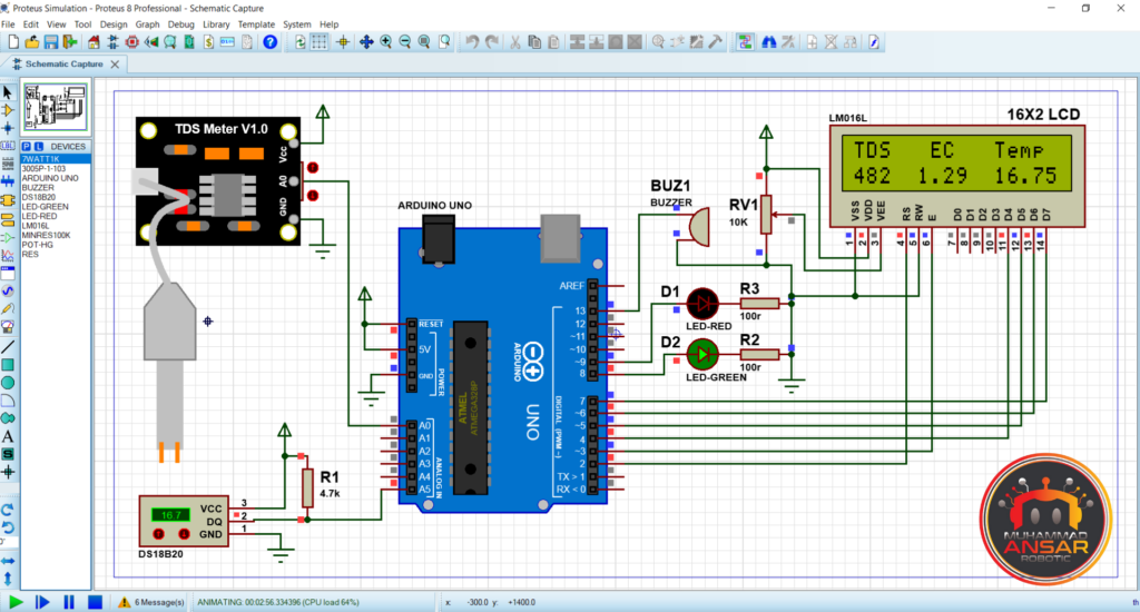
We started the TDS meter project in the Proteus 8.12 simulation by adding several elements to the virtual world. To measure the total dissolved solids in water, we interfaced the TDS sensor with the A0 pin using the Arduino UNO as the central controller. Furthermore, a temperature sensor was incorporated and set up with a 4.7k resistor pull-up configuration to consider the possible influence of temperature on electrical conductivity. Two LEDs—the red and green LEDs—as well as 100-ohm resistors were used in the circuit. A 16×2 LCD was used to show the temperature in degrees Celsius, the electrical conductivity in macrocimens per centimeter, and the TDS value in milligrams per liter. A buzzer was also incorporated for auditory alerts. We used the Arduino IDE to compile the Arduino code, create the hex-file, and then add the hex-file address to the Arduino simulation in order to mimic the project. The LCD first showed a notice indicating a 2000 ms delay during the simulation run, and then it showed the sensors’ real-time data. On the LCD’s second line, the TDS value, electrical conductivity, and temperature were displayed. Dynamic reactions to variations in the TDS value were incorporated in the simulation. For example, the red LED and the alarm would activate if the TDS value fell below 50 or rose beyond 700. In either case, the green LED would go out. On the other hand, the green LED illuminated to indicate drinking water when the TDS value was within the range of 50 to 700. The technology showed that it could give a thorough evaluation of water quality under simulated settings by taking into account the effect of temperature on electrical conductivity.
Circuit Diagram
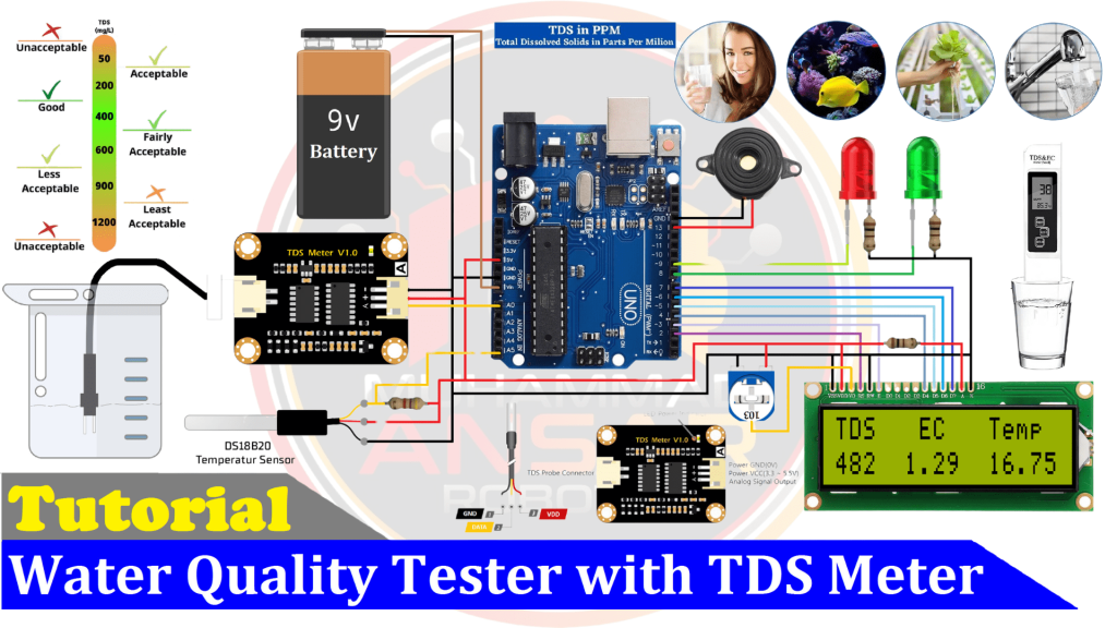
Our TDS meter project’s circuit diagram shows how parts are arranged methodically to measure the quality of the water. To start, we decided to use a 9V battery as the power source to provide the required power. The Arduino UNO, which acts as the primary controller for the system, is in the core of the circuit. To detect the total dissolved solids (TDS) in water, we used a TDS sensor. To take temperature fluctuations into account, we used a DS18B20 digital temperature sensor. To guarantee precise temperature readings, a 4.7k resistor was used to draw up the temperature sensor’s output. The components intended to test water quality are arranged methodically in the circuit diagram for our TDS meter project. First, we choose to deliver the required power using a 9V battery as the power source. The Arduino UNO, which functions as the system’s primary controller, is at the core of the circuit. In order to account for temperature changes, we used a DS18B20 digital temperature sensor in addition to a TDS sensor to detect the total dissolved solids in water. To guarantee precise temperature readings, the temperature sensor’s output was pushed up via a 4.7k resistor.
Arduino IDE Code
#include <LiquidCrystal.h> //Libraries
LiquidCrystal lcd(2, 3, 4, 5, 6, 7); //Arduino pins to lcd

#define tds_sensor A0
#define DS18B20_PIN  A5 // for Arduino microcontroller

#define G_led 8
#define R_led 9
#define buzzer 13

float aref = 4.3;
float ecCalibration = 1;

float ec = 0;
unsigned int tds = 0;

int raw_temp;
float waterTemp = 0;

void setup(){
pinMode(tds_sensor, INPUT);

pinMode(R_led,OUTPUT); // declare Red LED as output
pinMode(G_led,OUTPUT); // declare Green LED as output
pinMode(buzzer,OUTPUT); // declare Buzzer as output

lcd.begin(16, 2); // Configura lcd numero columnas y filas
lcd.clear();
lcd.setCursor (0,0);
lcd.print("   Welcome To   ");
lcd.setCursor (0,1);
lcd.print("TDS & Temp Meter");
delay(2000);
lcd.clear();
}

void loop(){

if(ds18b20_read(&raw_temp)) {
waterTemp = (float)raw_temp / 16;     // Convert temperature raw value into degree Celsius (temp in °C = raw/16)
}
float rawEc = analogRead(tds_sensor) * aref / 1024.0; // read the analog value more stable by the median filtering algorithm, and convert to voltage value
float temperatureCoefficient = 1.0 + 0.02 * (waterTemp - 25.0); // temperature compensation formula: fFinalResult(25^C) = fFinalResult(current)/(1.0+0.02*(fTP-25.0));
ec = (rawEc / temperatureCoefficient) * ecCalibration; // temperature and calibration compensation
tds = (133.42 * pow(ec, 3) - 255.86 * ec * ec + 857.39 * ec) * 0.5; //convert voltage value to tds value

lcd.clear();
lcd.setCursor(0,0);
lcd.print("TDS   EC   Temp");
lcd.setCursor(0,1);
lcd.print(tds);
lcd.setCursor(5,1);
lcd.print(ec, 2);
lcd.setCursor(11,1);
lcd.print(waterTemp,2);

if(tds<50 || tds>700){
digitalWrite(buzzer, HIGH);
digitalWrite(G_led, LOW); // Turn LED off.
digitalWrite(R_led, HIGH);  // Turn LED on.
delay(300);
}else{
digitalWrite(G_led, HIGH); // Turn LED on.
digitalWrite(R_led, LOW);  // Turn LED off.
}

digitalWrite(buzzer, LOW);
delay(500);
}

bool ds18b20_start(){bool ret = 0;
  digitalWrite(DS18B20_PIN, LOW);     // Send reset pulse to the DS18B20 sensor
  pinMode(DS18B20_PIN, OUTPUT);
  delayMicroseconds(500);             // Wait 500 us
  pinMode(DS18B20_PIN, INPUT);
  delayMicroseconds(100);             //wait to read the DS18B20 sensor response
  if (!digitalRead(DS18B20_PIN)) {
    ret = 1;                          // DS18B20 sensor is present
    delayMicroseconds(400);           // Wait 400 us
  }
  return(ret);
}

void ds18b20_write_bit(bool value){
  digitalWrite(DS18B20_PIN, LOW);
  pinMode(DS18B20_PIN, OUTPUT);
  delayMicroseconds(2);
  digitalWrite(DS18B20_PIN, value);
  delayMicroseconds(80);
  pinMode(DS18B20_PIN, INPUT);
  delayMicroseconds(2);
}

void ds18b20_write_byte(byte value){
  byte i;
  for(i = 0; i < 8; i++)
    ds18b20_write_bit(bitRead(value, i));
}

bool ds18b20_read_bit(void) {
  bool value;
  digitalWrite(DS18B20_PIN, LOW);
  pinMode(DS18B20_PIN, OUTPUT);
  delayMicroseconds(2);
  pinMode(DS18B20_PIN, INPUT);
  delayMicroseconds(5);
  value = digitalRead(DS18B20_PIN);
  delayMicroseconds(100);
  return value;
}

byte ds18b20_read_byte(void) {
  byte i, value;
  for(i = 0; i  <8; i++)
    bitWrite(value, i, ds18b20_read_bit());
  return value;
}

bool ds18b20_read(int *raw_temp_value) {
  if (!ds18b20_start())                     // Send start pulse
    return(0);                              // Return 0 if error
  ds18b20_write_byte(0xCC);                 // Send skip ROM command
  ds18b20_write_byte(0x44);                 // Send start conversion command
  while(ds18b20_read_byte() == 0);          // Wait for conversion complete
  if (!ds18b20_start())                     // Send start pulse
    return(0);                              // Return 0 if error
  ds18b20_write_byte(0xCC);                 // Send skip ROM command
  ds18b20_write_byte(0xBE);                 // Send read command
  *raw_temp_value = ds18b20_read_byte();    // Read temperature LSB byte and store it on raw_temp_value LSB byte
  *raw_temp_value |= (unsigned int)(ds18b20_read_byte() << 8);     // Read temperature MSB byte and store it on raw_temp_value MSB byte
  return(1);                                // OK --> return 1
}
Explanation
Our TDS meter project’s code offers a full range of features for measuring and displaying water quality metrics. First, the LCD’s LiquidCrystal library is added, and different pins for parts such the buzzer, TDS sensor, temperature sensor (DS18B20), and red and green LEDs are initialized. Then, the temperature, electrical conductivity, and TDS variables are initialized, along with the calibration variables. Pins are set up as input or output in the setup area, and the 16×2 LCD is initialized. With a 2000 ms delay, the first message appears on the LCD to give a preliminary indication of system readiness. Entering the loop, the code uses the DS18B20 sensor to measure temperature, the TDS sensor to measure electrical conductivity, and a preset algorithm to transform the electrical conductivity value into TDS. Next, the resulting values are shown on the LCD’s second line. A conditional check on the TDS variable is included in the code. The buzzer and Red LED are on while the Green LED is off if the TDS value is less than 50 or greater than 700. On the other hand, the Red LED and buzzer are disabled and the Green LED is triggered when the TDS value is between 50 and 700. The loop keeps running, pausing 500 ms in between each iteration. A function to read and get the temperature from the DS18B20 sensor is also included in the code. The user must choose the correct board (Arduino UNO) and port in the Arduino IDE in order to upload the code to the Arduino. The TDS meter project’s software is finished when the code is uploaded to the Arduino and the parameters are verified.
Hardware Testing
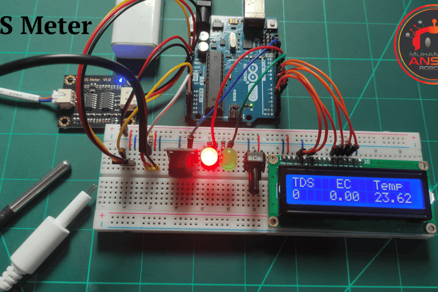
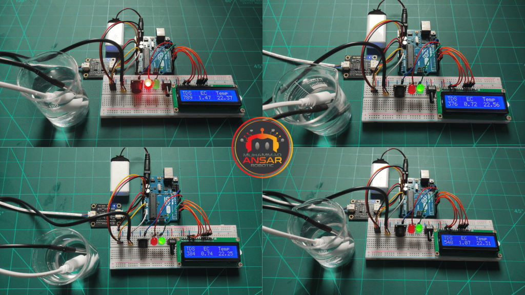
Our main goal in the hardware testing stage is to use the TDS meter, which is salt-dependent by nature, to measure the electrical conductivity of water. The TDS (Total Dissolved Solids) number is a vital indication of the overall quality of the water since it indicates the quantity of salt present in the water. Our measurements are provided in macrocimens per centimeter as well as milligrams per liter, providing a thorough understanding of the dissolved solids concentration of the water. We also record the water’s temperature in degrees Celsius as a crucial component of the testing procedure. Considering that temperature can affect the water’s conductivity, this extra parameter improves the accuracy of our evaluation of the water quality. Our TDS meter makes sure that the composition of the water is thoroughly evaluated by carefully monitoring these readings. This allows customers to make informed judgments on the water’s appropriateness and purity for different uses.
Conclusion
In conclusion, an affordable and simple way to check the quality of your water is to utilize the TDS meter that uses an Arduino temperature and TDS sensor. This project shows how different electrical components may be integrated to build a useful tool that can determine the total dissolved solids in a specific water sample. People may help raise awareness of clean water issues and maintain their own water quality testers by following the instructions provided in this blog article.
5 responses to “TDS Meter – Water Quality Tester”

assalamu Alaicum
wa alaikum assalam
Hi could you give me thé library of TDS sensor for Proteus this IS m’y email inchirahfatimazohra@gmail.com
can you give library of TDS sensor for proteus please?
asmaakhaled92751@gmail.comNo library is used in it


5 thoughts on “TDS Meter – Water Quality Tester”
 MUHAMMAD Zahid says:
assalamu Alaicum
- Fatima says:
Hi could you give me thé library of TDS sensor for Proteus this IS m’y email inchirahfatimazohra@gmail.com
Leave a Reply