
IOT And Manual Switch Control Home Appliances Using Firebase Server

Introduction
With home automation, customers may now remotely operate their appliances, which has grown in popularity. The goal of this project is to build a home automation system that makes use of manual switch control in addition to the Internet of Things (IoT). Firebase is used by the system to control home appliances, giving consumers remote device management capabilities. This tutorial will lead you through the necessary parts, the circuit schematic, the Arduino IDE code explanation, hardware testing, MIT App Inventor for the mobile app, and the project’s consequences in the end.
Components Required
- Solderless Breadboard
- Arduino NodeMCU
- Push Button x 4
- 4-Channel 5v Relay Module
- Male to Male Jumper Wires
- Male to Female Jumper Wires
- Bulb Holder x 2
- 220V LED Bulb x 2
- AC Fan 220V
- Socket Switch Board
- 5V 2Amp Power Adapter
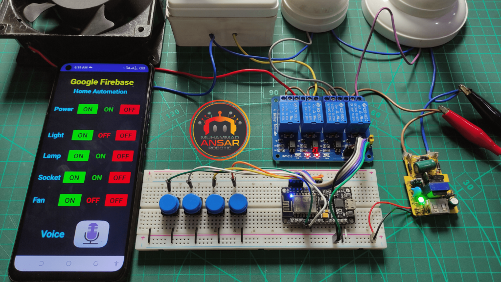
Circuit Diagram
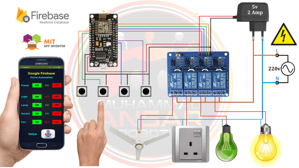
In this circuit diagram, Arduino NodeMCU is used as a microcontroller. Four push buttons are used for settings. Four channel 5 volts relay module is used for four loads. A 5 volts and 2 ampere adapter is used for power source. The main power source is 220 volts that is for our loads. For loads, we have used a fan, a switch and light bulbs. To operate other part of circuit, power adapter is used, that will provide 5 volts DC input. Make accurate connections for smooth working.
Arduino IDE Code
/*
 https://arduino.esp8266.com/stable/package_esp8266com_index.json
 */

#include <ESP8266WiFi.h>
#include <FirebaseESP8266.h>

#define ssid "M.Ansar"  //WiFi SSID
#define password "78612345"  //WiFi Password
#define FIREBASE_HOST "------------" //Your Firebase Project URL goes here without "http:" , "\" and "/"
#define FIREBASE_AUTH "----------------" //Your Firebase Auth Token

FirebaseData firebaseData;

// define the GPIO connected with Relays and switches
#define Relay1  D0 //GPIO 16
#define Relay2  D1 //GPIO 5
#define Relay3  D2 //GPIO 4
#define Relay4  D3 //GPIO 0

#define Switch1 10 //SD3
#define Switch2 9  //SD2
#define Switch3 12 //D5
#define Switch4 14 //D6

#define wifiLed D4 //GPIO 2

int load1=1, load2=1, load3=1, load4=1, Power;

void setup() {
Serial.begin(9600);

pinMode(Relay1, OUTPUT); digitalWrite(Relay1, HIGH);
pinMode(Relay2, OUTPUT); digitalWrite(Relay2, HIGH);
pinMode(Relay3, OUTPUT); digitalWrite(Relay3, HIGH);
pinMode(Relay4, OUTPUT); digitalWrite(Relay4, HIGH);

pinMode(wifiLed, OUTPUT);

pinMode(Switch1, INPUT_PULLUP);
pinMode(Switch2, INPUT_PULLUP);
pinMode(Switch3, INPUT_PULLUP);
pinMode(Switch4, INPUT_PULLUP);

WiFi.begin (ssid, password);
Firebase.begin(FIREBASE_HOST,FIREBASE_AUTH);
delay(100);
}

void loop() {

if (WiFi.status() != WL_CONNECTED){
    //Serial.println("WiFi Not Connected");
    digitalWrite(wifiLed, HIGH); //Turn off WiFi LED
  }
  else{
    //Serial.println("WiFi Connected");
    digitalWrite(wifiLed, LOW); //Turn on WiFi LED
}

Switch_Read();
if(Firebase.get(firebaseData,"/P1")) {
 if (firebaseData.dataType() == "string") {
 Power = firebaseData.stringData().toInt();
 }
}
Relays();

Switch_Read();
if(Firebase.get(firebaseData,"/L1")) {
 if (firebaseData.dataType() == "string") {
 load1 = firebaseData.stringData().toInt();
 }
}
Relays();

Switch_Read();
if(Firebase.get(firebaseData,"/L2")) {
 if (firebaseData.dataType() == "string") {
 load2 = firebaseData.stringData().toInt();
 }
}
Relays();

Switch_Read();
if(Firebase.get(firebaseData,"/L3")) {
 if (firebaseData.dataType() == "string") {
 load3 = firebaseData.stringData().toInt();
 }
}
Relays();

Switch_Read();
if(Firebase.get(firebaseData,"/L4")) {
 if (firebaseData.dataType() == "string") {
 load4 = firebaseData.stringData().toInt();
  }
 }
Relays();

}


void Switch_Read(){

     if(digitalRead(Switch1) == LOW){Power=0;
     update_power_status();
      load1 = !load1;
      Relays();
if(Firebase.setString(firebaseData, "/L1", String(load1))){
    Serial.println("PASSED");
    Serial.println("PATH: " + firebaseData.dataPath());
    Serial.println("TYPE: " + firebaseData.dataType());
    Serial.println("ETag: " + firebaseData.ETag());
    Serial.println("------------------------------------");
    Serial.println();
  }else{
    Serial.println("FAILED");
    Serial.println("REASON: " + firebaseData.errorReason());
    Serial.println("------------------------------------");
    Serial.println();
  }
      delay(300);
  }
else if(digitalRead(Switch2) == LOW){Power=0;
      update_power_status();
      load2 = !load2;
      Relays();
if(Firebase.setString(firebaseData, "/L2", String(load2))){
    Serial.println("PASSED");
    Serial.println("PATH: " + firebaseData.dataPath());
    Serial.println("TYPE: " + firebaseData.dataType());
    Serial.println("ETag: " + firebaseData.ETag());
    Serial.println("------------------------------------");
    Serial.println();
  }else{
    Serial.println("FAILED");
    Serial.println("REASON: " + firebaseData.errorReason());
    Serial.println("------------------------------------");
    Serial.println();
  }
 delay(300);
}

else if(digitalRead(Switch3) == LOW){Power=0;
      update_power_status();
      load3 = !load3;
      Relays();
if(Firebase.setString(firebaseData, "/L3", String(load3))){
    Serial.println("PASSED");
    Serial.println("PATH: " + firebaseData.dataPath());
    Serial.println("TYPE: " + firebaseData.dataType());
    Serial.println("ETag: " + firebaseData.ETag());
    Serial.println("------------------------------------");
    Serial.println();
  }
  else{
    Serial.println("FAILED");
    Serial.println("REASON: " + firebaseData.errorReason());
    Serial.println("------------------------------------");
    Serial.println();
  }
  delay(300);
 }

else if(digitalRead(Switch4) == LOW){Power=0;
      update_power_status();
      load4 = !load4;
      Relays();
if(Firebase.setString(firebaseData, "/L4", String(load4))){
    Serial.println("PASSED");
    Serial.println("PATH: " + firebaseData.dataPath());
    Serial.println("TYPE: " + firebaseData.dataType());
    Serial.println("ETag: " + firebaseData.ETag());
    Serial.println("------------------------------------");
    Serial.println();
 }else{
    Serial.println("FAILED");
    Serial.println("REASON: " + firebaseData.errorReason());
    Serial.println("------------------------------------");
    Serial.println();
  }
delay(300);
 }
}


void update_power_status(){
if(Firebase.setString(firebaseData, "/P1", String(Power))){
    Serial.println("PASSED");
    Serial.println("PATH: " + firebaseData.dataPath());
    Serial.println("TYPE: " + firebaseData.dataType());
    Serial.println("ETag: " + firebaseData.ETag());
    Serial.println("------------------------------------");
    Serial.println();
}else{
    Serial.println("FAILED");
    Serial.println("REASON: " + firebaseData.errorReason());
    Serial.println("------------------------------------");
    Serial.println();
}
}

void Relays(){
if(Power==0){
digitalWrite(Relay1, load1);
digitalWrite(Relay2, load2);
digitalWrite(Relay3, load3);
digitalWrite(Relay4, load4);
}else{
digitalWrite(Relay1, HIGH);
digitalWrite(Relay2, HIGH);
digitalWrite(Relay3, HIGH);
digitalWrite(Relay4, HIGH);
 }
}
Explanation
The given Arduino code is intended for use with an ESP8266-based NodeMCU home automation system, allowing control of household appliances via manual switches in addition to Internet of Things devices. The required libraries are first included in the code, such as the FirebaseESP8266 library for interacting with the Firebase Realtime Database and the ESP8266WiFi library for managing Wi-Fi connectivity. The code defines the specifics of the Firebase project, including the project URL and authentication token. The GPIO pins that are linked to the switches, relays, and LEDs are then specified. The hardware connectors on the NodeMCU board match these pins. Both the total power state (Power) and the load states (load1 through load4) are designated as variables.
The GPIO pins are set up for their intended uses, and the serial connection is established for debugging in the setup function. The NodeMCU tries to establish a connection with the Firebase server and the designated Wi-Fi network. It incorporates a little delay to enable reliable communications. The main loop updates the Wi-Fi LED in accordance with the state of the Wi-Fi connection, which it checks continually. Multiple calls are made to the Switch_Read function, which is in charge of keeping an eye on the manual switch inputs (Switches 1 through 4) and modifying the associated load states in response to switch pushes. It also activates the relays in accordance with the updated load statuses in the Firebase database. The Firebase database is updated with the current power state (Power) using the update_power_status function. Relay states are managed by the Relays function in accordance with the load and power states. The relays are configured to the current load states if the power is off (Power == 0). Every relay is off when the electricity is on.
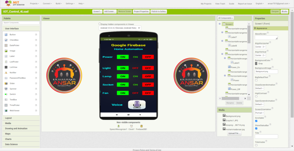
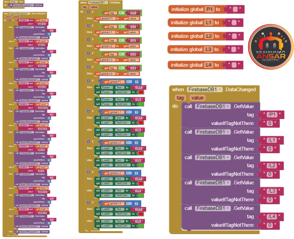
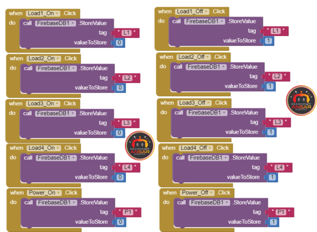
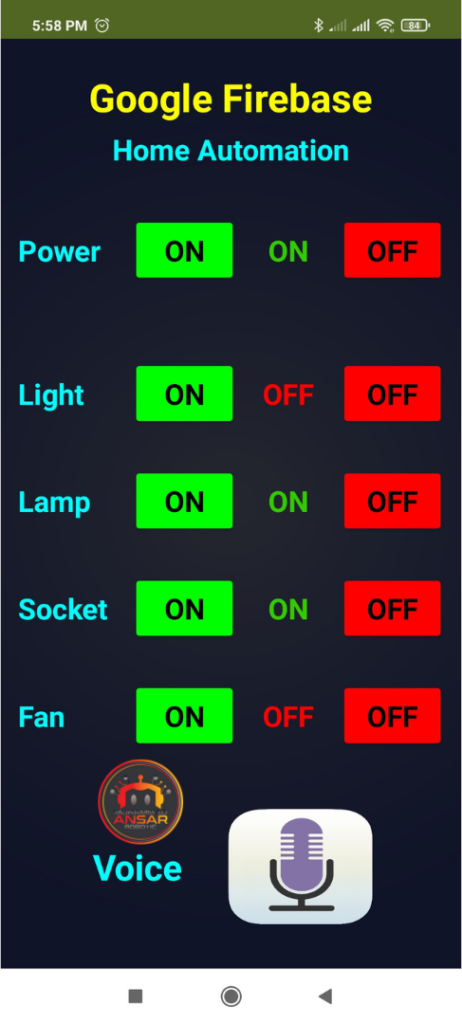
MIT App Inventor
The mobile application is built using MIT App inventor. Download the apk file and install it in your mobile. The mobile app has Power On/Off button. Light On/Off button. Lamp On/Off button. Socket On/Off button. Fan On/Off button. It also has voice control option. For voice controls, you need to say Light off it will turn off the light and when you will say Light on, it will turn on the light. Following are the commands settings for the App:-
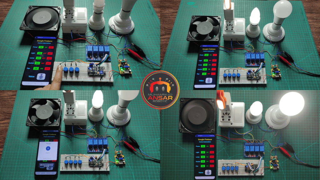
Hardware Testing
Make sure all of the parts are connected correctly after building the circuit. Turn on the system, check the manual switches, and keep an eye on Firebase’s modifications. To operate appliances remotely, use the smartphone app. Check to see if the relays react correctly to manual and app-based inputs.
Conclusion
Convenience and control are increased by home automation that makes use of manual switches and Firebase. For consumers looking for a flexible home automation system, this project provides a scalable and adaptable option. Experiment with different features and build the system to suit specific requirements. In addition to being user-friendly, home automation promotes energy efficiency and contemporary living.


Leave a Reply