Automatic Temperature Control System using Arduino

Introduction
Welcome to another great project from MArobotics! In this attempt, we’ll delve into the interesting area of automated systems to provide you with a full guide on developing an Automatic Temperature Control System using Arduino. In an increasingly automated and technologically advanced society, the capacity to regulate environmental elements such as temperature is crucial. Automatic temperature control systems are essential for maintaining ideal operating temperatures for equipment, guaranteeing comfort in living areas, and managing processes in industrial settings. Using a mix of sensors, and programming logic, we’ll build a system that can monitor ambient temperature and automatically modify a connected device, such as a fan, to maintain the appropriate temperature level. Let’s dive in!
Components Required
- Solderless Breadboard
- Arduino UNO
- 16×2 LCD Display
- IRFz44N Mosfet
- Push Button (x3)
- NTC 10k Thermistor Temperature Sensor
- 10k Variable Resistor
- 10k Resistor (x2)
- 100R Resistor (x2)
- Buzzer
- Male to Male Jumper Wires
- Hard Jumper Wire
- 12V DC Fan
- 12V 2Amp Power Adapter
Proteus Simulation
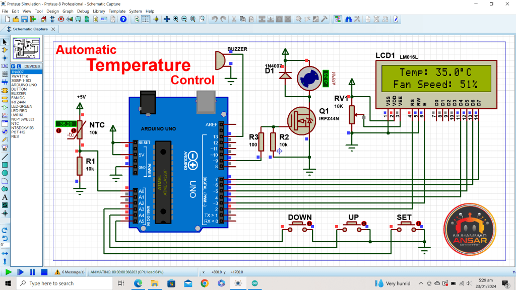
Before starting with the actual implementation, it is useful to simulate the circuit with software such as Proteus. This enables us to test the functioning and troubleshoot any problems before assembling the components. Open the simulation file on Proteus 8.12. This simulation begins with the utilization of an Arduino UNO microcontroller, serving as the microcontroller for our Automatic Temperature Control System. To sense temperature variations, we employ a 10k NTC thermistor, complemented by a 10k pull-down resistor. The system’s user interface is enhanced with three push buttons for temperature adjustment and an essential 16×2 LCD for data visualization. Ensuring optimal display contrast, a 10k potentiometer is integrated into the circuit. Efficient fan speed regulation is facilitated by the FET IRFZ44N, while a standard fan provides the necessary air circulation. Additionally, a buzzer is incorporated to sound an alarm when temperature thresholds are breached. Once the code is compiled in the Arduino IDE and the hex file is generated, it’s seamlessly integrated into the simulation environment. Through this simulation, users can observe the system’s functionality, from temperature readings and fan speed adjustments to setting modifications, all in a controlled virtual environment.
Circuit Diagram
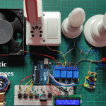
In the circuit diagram provided, the system is powered by a 220V power source, which is subsequently regulated by a 12V, 2A power adapter. An Arduino UNO microcontroller serves as the brains of the operation. A 10k thermistor, used as the temperature sensor, is connected to the microcontroller and pulled down by a 10k resistor. The user interface includes three push buttons for interaction and a 16×2 LCD for displaying information, with contrast adjustment facilitated by a 10k potentiometer. The LCD backlight pins are connected to the power supply, with a 100 ohm resistor in series to control brightness. A DC fan is employed for temperature regulation, with its negative terminal controlled by an N-channel FET, whose gate is connected to the microcontroller via a 10k pull-down resistor and a 100 ohm resistor from pin 9. Additionally, a buzzer is incorporated for audible alerts.

Arduino IDE Code
#include <EEPROM.h>
#include <LiquidCrystal.h>
LiquidCrystal lcd(2, 3, 4, 5, 6, 7);

#define ThermistorPin A0 // for Arduino microcontroller

#define bt_set  A3
#define bt_up   A4
#define bt_down A5

#define fan 9
#define buzzer 13

long ADC_Value;
float R1 = 10000; // value of R1 on board
float logR2, R2, T;

//steinhart-hart coeficients for thermistor
float c1 = 0.001129148, c2 = 0.000234125, c3 = 0.0000000876741;

float setL_temp = 30.5;
float setH_temp = 39.5;
float temp=0;

int duty_cycle;
int Set=0, flag=0, flash=0;

void setup() {// put your setup code here, to run once:

pinMode(ThermistorPin, INPUT);

pinMode(bt_set,  INPUT_PULLUP);
pinMode(bt_up,   INPUT_PULLUP);
pinMode(bt_down, INPUT_PULLUP);

pinMode(fan, OUTPUT);
pinMode(buzzer, OUTPUT);

lcd.begin(16, 2); // Configura lcd numero columnas y filas
lcd.clear();
lcd.setCursor (0,0);
lcd.print("   Welcome To   ");
lcd.setCursor (0,1);
lcd.print("  Temp Control  ");

if(EEPROM.read(0)==0){}
else{
EEPROM.put(10, setL_temp);
EEPROM.put(15, setH_temp);
EEPROM.write(0, 0);
}
EEPROM.get(10, setL_temp);
EEPROM.get(15, setH_temp);

delay(2000); //wait 1000 mS for next measure
lcd.clear();
}

void loop(){

ADC_Value=0;
for(int i=0; i<100; i++) {
ADC_Value = ADC_Value+analogRead(ThermistorPin);
delay(1);
}

ADC_Value=ADC_Value/100;
R2 = R1 * (1023.0 / (float)ADC_Value - 1.0); //calculate resistance on thermistor
logR2 = log(R2);
temp = (1.0 / (c1 + c2*logR2 + c3*logR2*logR2*logR2)); // temperature in Kelvin
temp = temp - 273.15; //convert Kelvin to Celcius

int value1 = temp*10;
int value2 = setL_temp*10;
int value3 = setH_temp*10;

duty_cycle = map(value1, value2, value3, 0, 100);
if(duty_cycle>100)duty_cycle=100;
if(duty_cycle<0)duty_cycle=0;

if(temp<setL_temp){digitalWrite(fan, 0);}
              else{analogWrite(fan, (duty_cycle*2)+55); }

if(temp>setH_temp){digitalWrite(buzzer, HIGH);  delay(100);}

if(digitalRead(bt_set)==0){
digitalWrite(buzzer, HIGH);
 if(flag==0){ flag=1;
  Set=Set+1;
  if(Set>2){Set=0; flash=0;}
delay(200);
 }
}else{flag=0;}

if(digitalRead(bt_up)==0){
digitalWrite(buzzer, HIGH);
if(Set==1){setL_temp = setL_temp+.1;EEPROM.put(10, setL_temp);}
if(Set==2){setH_temp = setH_temp+.1;EEPROM.put(15, setH_temp);}
delay(10);
}

if(digitalRead(bt_down)==0){
digitalWrite(buzzer, HIGH);
if(Set==1){setL_temp = setL_temp-.1;EEPROM.put(10, setL_temp);}
if(Set==2){setH_temp = setH_temp-.1;EEPROM.put(15, setH_temp);}
delay(10);
}

if(Set==0){

lcd.setCursor(0,0);
lcd.print("  Temp: ");
lcd.print(temp,1);
lcd.write(223);
lcd.print("C   ");

lcd.setCursor(0,1);
lcd.print(" Fan Speed:");
if(duty_cycle<100)lcd.print(" ");
lcd.print(duty_cycle);
lcd.print("%   ");

}else{
lcd.setCursor(0,0);
lcd.print("  Setting Mode  ");

lcd.setCursor(0,1);
lcd.print("L:");
if(Set==1 && flash==1){lcd.print("    ");}
else{lcd.print(setL_temp,1);}
lcd.print("C  ");

lcd.setCursor(9,1);
lcd.print("H:");
if(Set==2 && flash==1){lcd.print("    ");}
else{lcd.print(setH_temp,1);}
lcd.print("C  ");
}

if(Set>0){flash=!flash;}
delay(1); //wait 1 mS for next measure
digitalWrite(buzzer, LOW);
}
Explanation
Libraries and LCD Setup: The code begins by incorporating the essential libraries, such as EEPROM and LiquidCrystal, for storing and displaying data. The LCD pins are specified, and the LCD is set up with its dimensions.
Variable Declarations: Several variables are declared for storing ADC results, resistance calculations, temperature readings, setting temperature thresholds, controlling fan speed using a duty cycle, and displaying flags.
Setup Function: The setup function configures the thermistor pin, temperature threshold buttons, fan, and buzzer. If this is the first time the LCD is used, it shows a welcome message and initializes using the default temperature readings from EEPROM.
Loop Function:
- Temperature Reading: ADC values are averaged over 100 readings to ensure consistent analog input from the thermistor. Using this result, the Steinhart-Hart equation is used to compute the thermistor’s resistance and, in turn, the temperature in Celsius. Fan Control: The fan is regulated based on the current temperature and the specified temperature thresholds to keep the temperature within the desired range. The duty cycle of the fan is modified accordingly.
- Buzzer Activation: If the temperature rises beyond the high level, the buzzer sounds to inform the user.
- Button Handling: Buttons are checked for human interaction while adjusting the established temperature thresholds. Long presses are used to toggle between setting the lower and upper temperature limits.
- LCD Display: The LCD is updated to show the current temperature and fan speed, and while in setting mode, it shows the current setting (lower or upper threshold) with blinking to indicate which value is being changed.
- Buzzer deactivation: After hearing an alarm sound, the buzzer is switched off.
Delay and Flag Management: There are minor delays while debouncing buttons to ensure seamless functioning. During setup mode, flags are utilized to control button behavior and toggle the display.
Hardware Testing
We’ll test the hardware after we’ve completed the circuit on the breadboard and uploaded the Arduino code. This includes ensuring that the system properly monitors temperature, displays it on the LCD, and activates the fan as intended.


Conclusion
To summarize, thanks to MArobotics, we were able to successfully build an Automatic Temperature Control System using Arduino. This project provides us with a useful tool for controlling temperature in a variety of settings while also providing practical insights into electronics and programming. With limitless applications, this system demonstrates the potential of ingenuity and imagination in the field of DIY electronics. Keep exploring and developing with MArobotics; the possibilities are limitless!
2 responses to “Automatic Temperature Control System using Arduino”

Hello,
It’s nice PID application !
But I have need this same for the inverse PID for the BBQ, decrease RPM when the temps its high and increase RPM when temp sit low.
Thanks for your help and mod line code Arduino.Best regard’s
Richard

ok i will try
2 thoughts on “Automatic Temperature Control System using Arduino”
Hello,
It’s nice PID application !
But I have need this same for the inverse PID for the BBQ, decrease RPM when the temps its high and increase RPM when temp sit low.
Thanks for your help and mod line code Arduino.Best regard’s
Richard


Leave a Reply