Automatic Solar Tracker System Using Arduino, LDR And Servo Motor
Introduction
Solar power comes out as a renewable and environmentally beneficial alternative as the globe welcomes the move to sustainable energy sources. An Automatic Solar Tracker System is a game changer for increasing the efficiency of solar panels. This project digs into the development of an Arduino-based solar tracker system that detects sunlight using Light Dependent Resistors (LDR) and changes the position of the solar panel using a servo motor. As a consequence, a clever and dynamic system is created that constantly aligns the solar panel orthogonal to the sun’s beams, improving energy gathering. Join MArobotics on this adventure as we investigate how to build a solar tracker system.
Components Required
- 5mm Acrylic Sheet (30cm x 20cm)
- VPC Cardboard (5mm thickness)
- Arduino UNO
- LDR Sensors (x2) – Light Dependent Resistors
- Mini Servo Motor (SG90)
- USB DC 1~5V to DC 5V Voltage Step-Up Boost Module
- LiPo Battery Charger Module (Mini TP4056 IC)
- On/Off Switch
- 18650 Battery Holder (1 Cell)
- 18650 Battery Cell (3.7V)
Proteus Simulation
This simulation examines the Automatic Solar Tracker System, which was built with Proteus 8. The system’s purpose is to actively follow the sun’s position in order to ensure that a solar panel remains optimally positioned for the greatest energy harvesting. This simulation shows how an Arduino UNO, LDR sensors, resistors, and a servo motor work together to provide precise sun tracking.
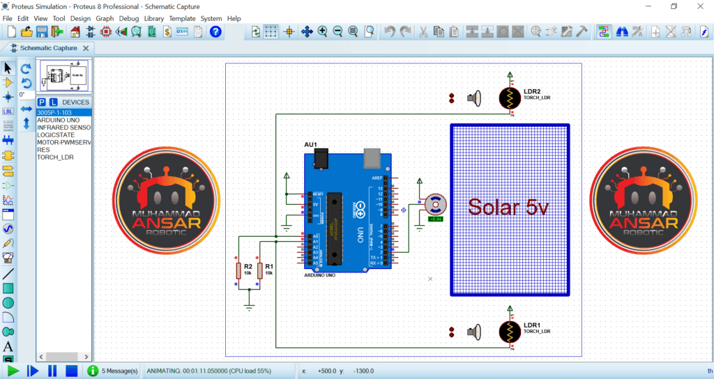
Compiling the code in the Arduino IDE is the first step in the simulation. This code allows the servo motor and the LDR sensors to operate together by coordinating their actions. At first, the servo motor is angled ninety degrees, and it remains motionless until the light reaching both LDR sensors is equal.
When a difference in light reception is found between the two LDR sensors, the simulation shows the intelligence of the system. The servo motor moves quickly to the side with higher light exposure as soon as one sensor detects a greater amount of light than the other. The servo motor stops when both sensors detect the same quantity of light, which is the result of this dynamic adjustment.
The efficiency with which the system follows the sun’s location as it rises, sets, or moves across the sky demonstrates its possibilities. The servo motor precisely moves the solar panel to keep it aligned with the sun by moving a light source nearer to one of the LDR sensors. When the two LDR sensors detect the same quantity of light, the system makes sure that the panel stays exactly perpendicular to the sun’s beams, which maximizes the efficiency of energy collecting.
Circuit Diagram
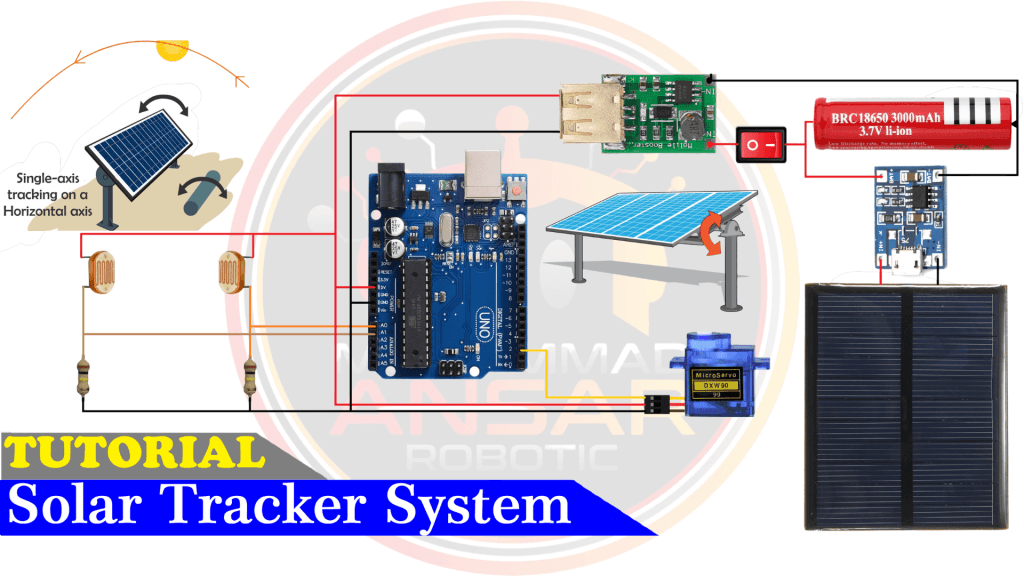
The circuit diagram that is included gives us an understanding of the hardware arrangement that serves as the foundation for our Automatic Solar Tracker System. A 3-watt, 5-volt solar panel serves as the main energy source for the system. We include a LiPo Battery Charger Module Mini TP4056 IC, which is powered by a 3.7-volt cell and has an on/off switch for control, to ensure the effective management of this energy.
A DC-DC 3.7-volt to 5-volt converter is used to provide 5 volts to power the essential parts, which include an MG90 servo motor, two Light Dependent Resistor (LDR) sensors, and an Arduino UNO, in order to maintain a consistent power distribution. Light Depending Resistors, or LDR sensors, are essential because they can identify variations in light intensity caused by changes in sunshine. The LDR sensors are pulled down using 100-kilo ohm resistors to guarantee their operation.
Arduino IDE Code
#include <Servo.h> //includes the servo library
Servo myservo;
#define ldr1 A0 // set ldr 1 Analog input pin of East ldr as an integer
#define ldr2 A1 // set ldr 2 Analog input pin of West ldr as an integer
int pos = 90; // initial position of the Horizontal movement controlling servo motor
int tolerance = 20; // allowable tolerance setting - so solar servo motor isn't constantly in motion

void setup(){
myservo.attach(2); // attaches the servo on digital pin 2 to the horizontal movement servo motor
pinMode(ldr1, INPUT); //set East ldr pin as an input
pinMode(ldr2, INPUT); //set West ldr pin as an input
myservo.write(pos); // write the starting position of the horizontal movement servo motor

delay(1000); // 1 second delay to allow the solar panel to move to its staring position before comencing solar tracking
}
void loop(){
int val1 = analogRead(ldr1); // read the value of ldr 1
int val2 = analogRead(ldr2); // read the value of ldr 2

if((abs(val1 - val2) <= tolerance) || (abs(val2 - val1) <= tolerance)) {
//no servo motor horizontal movement will take place if the ldr value is within the allowable tolerance
}else {
if(val1 > val2) // if ldr1 senses more light than ldr2
{
pos = pos+1; // decrement the 90 degree poistion of the horizontal servo motor - this will move the panel position Eastward
}
if(val1 < val2) // if ldr2 senses more light than ldr1
{
pos = pos-1; // increment the 90 degree position of the horizontal motor - this will move the panel position Westward
 }
}

if(pos > 180) {pos = 180;} // reset the horizontal postion of the motor to 180 if it tries to move past this point
if(pos < 0) {pos = 0;} // reset the horizontal position of the motor to 0 if it tries to move past this point
myservo.write(pos); // write the starting position to the horizontal motor
delay(50);
}Explanation:
The servo motor is initialized as “myservo,” two pins, A0 and A1, are set up for the LDR sensors, and the code starts by importing the servo motor library. It also creates a variable called “position,” which is initialized to 90 degrees and represents the servo motor’s starting position. Introduced and set to 20, the “tolerance” variable is essential in deciding when to operate the servo motor in response to inputs from the LDR sensor. The servo motor will modify its position if there is a deviation bigger than this tolerance between the absolute values obtained from the two LDR sensors.
Within the setup function, pin 2 is initialized for “myservo,” and the LDR sensor pins are configured to INPUT mode. The servo motor’s starting position is set at 90 degrees in its original configuration. There is a 1000 ms wait before the code runs in the loop. The code reads the two LDR sensors’ analog readings during the loop and stores them in “var1” and “var2.” The servo motor’s readiness to move is then decided by a sequence of conditional statements that are carried out in response to variations in the tolerance value and the LDR sensor readings. The servo motor modifies position if the discrepancy exceeds tolerance.
Several possibilities are taken into consideration in the code, such as whether LDR sensor 1 or LDR sensor 2 receives more light. It modifies the “position” variable little by little, making sure it stays between 0 and 180 degrees. The “position” variable is used to update the position of the servo motor, and the loop is kept running with a 100 ms delay. The algorithm continually modifies the orientation of the solar panel to keep it in the best possible alignment with the sun’s position as determined by the LDR sensors. You may adjust the delay to change how quickly the solar panel moves.
Hardware Testing
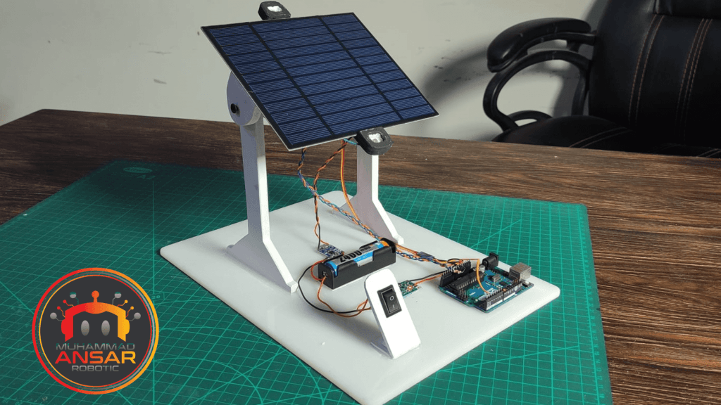
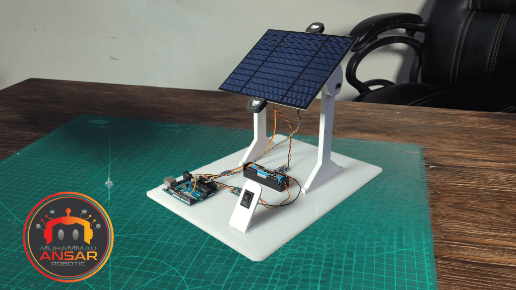
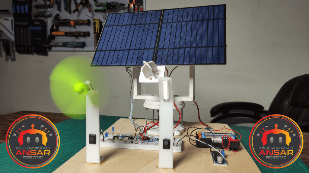
The code controls the solar tracking system’s operations after it is uploaded to the Arduino UNO, allowing for accurate and dynamic sun tracking. The efficiency of this code is seen in the hardware testing step that follows, when the system’s motions are monitored to maximize energy collection by aligning the solar panels as optimally as possible.
Conclusion
In summary, the Automatic Solar Tracker System provides a clever and effective way to maximize the energy production of solar panels. It is powered by an Arduino UNO, LDR sensors, and a servo motor. In addition to optimizing energy output, this technology helps create a more sustainable and environmentally friendly future by cleverly altering the direction of the solar panels.
3 responses to “Automatic Solar Tracker System Using Arduino, LDR And Servo Motor”

Nice

thank you

It’s amazing to go to see this website and reading the
views of all friends concerning this piece of writing, while I am
also eager of getting familiarity.
3 thoughts on “Automatic Solar Tracker System Using Arduino, LDR And Servo Motor”
Nice
It’s amazing to go to see this website and reading the
views of all friends concerning this piece of writing, while I am
also eager of getting familiarity.


Leave a Reply