
Real Time Clock Based Automatic Home Appliances Control

Introduction
Automation has emerged as a crucial component of convenience in our fast-paced life. Envision a residence where your appliances are skillfully managed according to the time of day. This blog post describes how to use an Arduino Uno to create an autonomous household appliance control system that is based on a real-time clock (RTC). Your everyday routine will be more efficient if you use this project to plan the activation and deactivation of your household appliances. We can set 4 timers in 24 hours through this project.
Components Required
- Solderless Breadboard
- Arduino UNO
- 16×2 LCD Display
- Push Button
- RTC DS3231 Module
- 100R Resistor
- 4.7k Resistor
- 1k Resistor
- Buzzer
- 1-Channel 5V Relay Module
- Male to Male Jumper Wires
- Male to Female Jumper Wires
- Bulb Holder
- 220V LED Bulb
- 5V 2Amp Power Adapter
Proteus Simulation
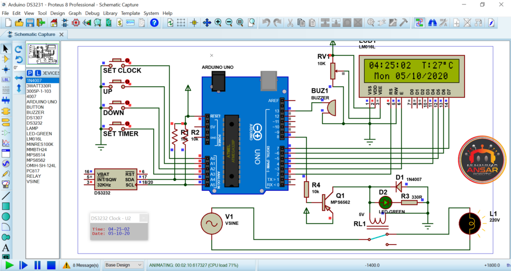
In the simulation, we used an Arduino Uno and a few other parts to build an autonomous household appliance control system based on real-time clocks (RTCs). Four push buttons, a relay module, a 16×2 LCD display, a DS3231 RTC module, a buzzer, and a light serving as the output device are the main parts. The system’s power supply was configured to provide 220V. The first step in the simulation procedure was to create a hex-file from the Arduino IDE code, which enabled us to model the functionality of the project. Up to four timers could be configured to automatically activate and deactivate the linked load on a predetermined schedule. The code also provided options for adjusting the clock and date. The simulation ran, and the date, temperature, and current time were shown on the LCD display. The clock, date, and timer configuration were all done via the push buttons. When you pressed the “Set Clock” button, for example, the variables for hours, minutes, seconds, day, date, month, and year began to blink one after the other. The buttons labeled “UP” and “DOWN” might be used to change these settings. Up to four timers may be configured with ease thanks to the “Set Timer” button. Users might arrange the activation and deactivation of the linked load by using the on and off times of each timer. The simulation showed how the load changed its state according to the defined schedule, turning on and off in response to the set timings. It’s important to note that users may establish up to four timers in a day because the specified timers operated on a 24-hour cycle. The simulation successfully demonstrated how the relay module, push buttons, and real-time clock interact to intelligently regulate the attached load.
Circuit Diagram
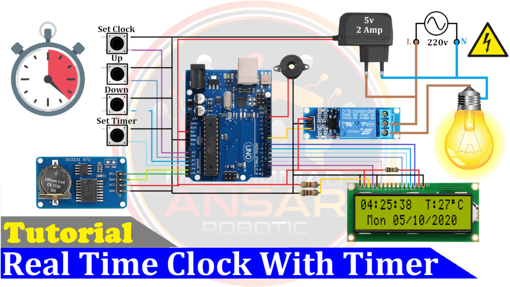
The real-time clock-based automated home appliance control system’s circuit diagram is painstakingly created to smoothly combine several parts. The Arduino Uno, four pushbuttons, a 16×2 LCD, an RTC module (DS3231), and a relay module for 5V switching of a 220V load are the main parts. The Arduino Uno serves as the primary controller, and its four push buttons are arranged in a way that makes it easy for users to enter information to establish timers and set the clock. Accurate real-time clock capability is provided by the DS3231 RTC module, which shows the date, temperature, and time on the 16×2 LCD. Pins 4 and 7 of the LCD layout are linked to ground and positive, respectively, while pins 15 and 16 are used as the anode and cathode for the backlight. For the correct contrast setting, a 100-ohm resistor is added in series with the positive end of the anode and the cathode is directly grounded. The relay module serves as the 220V load’s switching mechanism and runs on 5 volts. The complete system is powered by a 5V, 2Amp power adaptor, which guarantees stability and dependability. The line is connected to the relay’s common point, and the 220V source is connected to the neutral load. The circuit for intelligent control is completed when the ordinarily open (NO) contact of the relay is connected to the load.
Arduino IDE Code
#include <DS3231.h>//Memanggil RTC3231 Library
#include <Wire.h>  // i2C Conection Library
#include <LiquidCrystal.h> //Libraries
#include <EEPROM.h>

LiquidCrystal lcd(2, 3, 4, 5, 6, 7); //Arduino pins to lcd

#define bt_clock  A0
#define bt_up     A1
#define bt_down   A2
#define bt_timer  A3

#define relay 8
#define buzzer 13

// Init DS3231
DS3231  rtc(SDA, SCL);

// Init a Time-data structure
Time  t; //pencacah string time()

int hh = 0, mm = 0, ss = 0, dd = 0, bb = 0, set_day;
int yy = 0;
String Day = "  ";

int StartHH  = 0, StartMM  = 0, FinishHH  = 0, FinishMM  = 0, setMode = 0, setAlarm = 0, alarmMode=1;
int Start1HH, Start1MM, Finish1HH, Finish1MM;
int Start2HH, Start2MM, Finish2HH, Finish2MM;
int Start3HH, Start3MM, Finish3HH, Finish3MM;
int Start4HH, Start4MM, Finish4HH, Finish4MM;

int timer1, timer2, timer3, timer4;

int stop =0, mode=0, flag=0;

void setup(){
rtc.begin(); // memulai koneksi i2c dengan RTC

pinMode(bt_clock, INPUT_PULLUP);
pinMode(bt_up,    INPUT_PULLUP);
pinMode(bt_down,  INPUT_PULLUP);
pinMode(bt_timer, INPUT_PULLUP);

pinMode(relay, OUTPUT);
digitalWrite(relay, HIGH);

pinMode(buzzer, OUTPUT);

  lcd.begin(16, 2); // Configura lcd numero columnas y filas
  lcd.setCursor(0,0);  //Show "TIME" on the LCD

  lcd.setCursor (0,0);
  lcd.print(" Real Time Clock ");
  lcd.setCursor (0,1);
  lcd.print("  4Timer 1Relay  ");
  delay (2000);
  lcd.clear();

stop=EEPROM.read(50);
if(stop==0){
}else{
mode=1;WriteEeprom ();delay (20);
mode=2;WriteEeprom ();delay (20);
mode=3;WriteEeprom ();delay (20);
mode=4;WriteEeprom ();delay (20);
mode=0;
}
EEPROM.write(50,0);

ReadEeprom();
//Set RTC Untuk Pertama kali
//rtc.setDOW(2);     // Set Day-of-Week to SUNDAY
//rtc.setTime (00, 9, 50);
//rtc.setDate(12, 11, 2017);
}

void loop(){
t = rtc.getTime();
Day = rtc.getDOWStr(1);

if (setMode == 0){
hh = t.hour,DEC;
mm = t.min,DEC;
ss = t.sec,DEC;
dd = t.date,DEC;
bb = t.mon,DEC;
yy = t.year,DEC;
//if(t.hour>12){hh=t.hour-12;}// for removing 24 houre
//else{hh=t.hour;}
}

  if(setAlarm==0){
  lcd.setCursor(0,0);
  lcd.print((hh/10)%10);
  lcd.print(hh % 10);
  lcd.print(":");
  lcd.print((mm/10)%10);
  lcd.print(mm % 10);
  lcd.print(":");
  lcd.print((ss/10)%10);
  lcd.print(ss % 10);
  lcd.print("  T:");
  lcd.print(rtc.getTemp(),0);
  lcd.write(223);
  lcd.print("C");
  lcd.print("  ");

  lcd.setCursor(1,1);
  lcd.print(Day);
  lcd.print(" ");
  lcd.print((dd/10)%10);
  lcd.print(dd % 10);
  lcd.print("/");
  lcd.print((bb/10)%10);
  lcd.print(bb % 10);
  lcd.print("/");
  lcd.print((yy/1000)%10);
  lcd.print((yy/100)%10);
  lcd.print((yy/10)%10);
  lcd.print(yy % 10);
  }


setupClock();
setTimer();
delay (100);
blinking();

//Timer1 ON
if (timer1==1 && alarmMode==1 && hh==Start1HH && mm==Start1MM)  {digitalWrite(relay, LOW);}
//Timer1 OFF
if (timer1==1 && alarmMode==1 && hh==Finish1HH && mm==Finish1MM){digitalWrite(relay, HIGH);}

//Timer2 ON
if (timer2==1 && alarmMode==1 && hh==Start2HH && mm==Start2MM)  {digitalWrite(relay, LOW);}
//Timer2 OFF
if (timer2==1 && alarmMode==1 && hh==Finish2HH && mm==Finish2MM){digitalWrite(relay, HIGH);}

//Timer3 ON
if (timer3==1 && alarmMode==1 && hh==Start3HH && mm==Start3MM)  {digitalWrite(relay, LOW);}
//Timer3 OFF
if (timer3==1 && alarmMode==1 && hh==Finish3HH && mm==Finish3MM){digitalWrite(relay, HIGH);}

//Timer4 ON
if (timer4==1 && alarmMode==1 && hh==Start4HH && mm==Start4MM)  {digitalWrite(relay, LOW);}
//Timer4 OFF
if (timer4==1 && alarmMode==1 && hh==Finish4HH && mm==Finish4MM){digitalWrite(relay, HIGH);}

delay (100);
digitalWrite(buzzer, LOW);
}

void blinking (){
//BLINKING SCREEN
//Set Clock
if (setAlarm <2 && setMode == 1){lcd.setCursor(0,0);  lcd.print("  ");}
if (setAlarm <2 && setMode == 2){lcd.setCursor(3,0);  lcd.print("  ");}
if (setAlarm <2 && setMode == 3){lcd.setCursor(6,0);  lcd.print("  ");}
if (setAlarm <2 && setMode == 4){lcd.setCursor(1,1);  lcd.print("   ");}
if (setAlarm <2 && setMode == 5){lcd.setCursor(5,1);  lcd.print("  ");}
if (setAlarm <2 && setMode == 6){lcd.setCursor(8,1);  lcd.print("  ");}
if (setAlarm <2 && setMode == 7){lcd.setCursor(11,1); lcd.print("    "); }

//Set Timer
if (setMode == 0 && setAlarm == 1 && mode==0){lcd.setCursor(2,1); lcd.print("  "); }
if (setMode == 0 && setAlarm == 2 && mode==0){lcd.setCursor(6,1); lcd.print("  "); }
if (setMode == 0 && setAlarm == 3 && mode==0){lcd.setCursor(10,1); lcd.print("  "); }
if (setMode == 0 && setAlarm == 4 && mode==0){lcd.setCursor(13,1); lcd.print("  "); }

if (setMode == 0 && setAlarm == 1 && mode>0){lcd.setCursor(11,0); lcd.print("  "); }
if (setMode == 0 && setAlarm == 2 && mode>0){lcd.setCursor(14,0); lcd.print("  "); }
if (setMode == 0 && setAlarm == 3 && mode>0){lcd.setCursor(11,1); lcd.print("  "); }
if (setMode == 0 && setAlarm == 4 && mode>0){lcd.setCursor(14,1); lcd.print("  "); }
}

//Seting Jam ,Tanggal,Alarm/Timer
void setupClock (void) {

    if (setMode == 8){
    lcd.setCursor (0,0);
    lcd.print ("Set Time Finish ");
    lcd.setCursor (0,1);
    lcd.print ("Set Date Finish ");
    delay (1000);
    rtc.setTime (hh, mm, ss);
    rtc.setDate (dd, bb, yy);
    lcd.clear();
    setMode = 0;
    }

 if (setAlarm >0){alarmMode=0;}

 if(digitalRead (bt_clock) == 0 && flag==0) {flag=1;
 if(setAlarm>0){WriteEeprom(); setAlarm=1; mode =5;}
 else{setMode = setMode+1;}
 digitalWrite(buzzer, HIGH);
 }

 if(digitalRead (bt_timer) == 0 && flag==0){flag=1;
 if(setMode>0){setMode=8;}
  else{
  setAlarm = setAlarm+1;
  if(setAlarm>4){setAlarm=1;
  WriteEeprom ();
  mode=mode+1;
  ReadEeprom();
  }
  }
  lcd.clear();
  digitalWrite(buzzer, HIGH);
  }

    if(setAlarm == 1 && mode==5){
    lcd.setCursor (0,0);
    lcd.print ("Set Timer Finish");
    lcd.setCursor (0,1);
    lcd.print ("-EEPROM Updated-");
    delay (2000);
    lcd.clear();
    setAlarm=0;
    mode =0;
    alarmMode=1;
    }

if(digitalRead (bt_clock) == 1 && digitalRead (bt_timer) == 1){flag=0;}

 if(digitalRead (bt_up) == 0){
            if (setAlarm<2 && setMode==1)hh=hh+1;
            if (setAlarm<2 && setMode==2)mm=mm+1;
            if (setAlarm<2 && setMode==3)ss=ss+1;
            if (setAlarm<2 && setMode==4)set_day=set_day+1;
            if (setAlarm<2 && setMode==5)dd=dd+1;
            if (setAlarm<2 && setMode==6)bb=bb+1;
            if (setAlarm<2 && setMode==7)yy=yy+1;
            //Timer
            if (mode==0 && setMode==0 && setAlarm==1)timer1=1;
            if (mode==0 && setMode==0 && setAlarm==2)timer2=1;
            if (mode==0 && setMode==0 && setAlarm==3)timer3=1;
            if (mode==0 && setMode==0 && setAlarm==4)timer4=1;

            if (mode>0 && setMode==0 && setAlarm==1)StartHH=StartHH+1;
            if (mode>0 && setMode==0 && setAlarm==2)StartMM=StartMM+1;
            if (mode>0 && setMode==0 && setAlarm==3)FinishHH=FinishHH+1;
            if (mode>0 && setMode==0 && setAlarm==4)FinishMM=FinishMM+1;

if(hh>23)hh=0;
if(mm>59)mm=0;
if(ss>59)ss=0;
if(set_day>7)set_day=0;
if(dd>31)dd=0;
if(bb>12)bb=0;
if(yy>2030)yy=2000;
if(StartHH>23)StartHH=0;
if(StartMM>59)StartMM=0;
if(FinishHH>23)FinishHH=0;
if(FinishMM>59)FinishMM=0;
rtc.setDOW(set_day);
digitalWrite(buzzer, HIGH);
 }

if(digitalRead (bt_down) == 0){
            if (setAlarm<2 && setMode==1)hh=hh-1;
            if (setAlarm<2 && setMode==2)mm=mm-1;
            if (setAlarm<2 && setMode==3)ss=ss-1;
            if (setAlarm<2 && setMode==4)set_day=set_day-1;
            if (setAlarm<2 && setMode==5)dd=dd-1;
            if (setAlarm<2 && setMode==6)bb=bb-1;
            if (setAlarm<2 && setMode==7)yy=yy-1;
            //Timer
            if (mode==0 && setMode==0 && setAlarm==1)timer1=0;
            if (mode==0 && setMode==0 && setAlarm==2)timer2=0;
            if (mode==0 && setMode==0 && setAlarm==3)timer3=0;
            if (mode==0 && setMode==0 && setAlarm==4)timer4=0;

            if (mode>0 && setMode==0 && setAlarm==1)StartHH=StartHH-1;
            if (mode>0 && setMode==0 && setAlarm==2)StartMM=StartMM-1;
            if (mode>0 && setMode==0 && setAlarm==3)FinishHH=FinishHH-1;
            if (mode>0 && setMode==0 && setAlarm==4)FinishMM=FinishMM-1;

if(hh<0)hh=23;
if(mm<0)mm=59;
if(ss<0)ss=59;
if(set_day<0)set_day=7;
if(dd<0)dd=31;
if(bb<0)bb=12;
if(yy<0)yy=2030;
if(StartHH<0)StartHH=23;
if(StartMM<0)StartMM=59;
if(FinishHH<0)FinishHH=23;
if(FinishMM<0)FinishMM=59;
rtc.setDOW(set_day);
digitalWrite(buzzer, HIGH);
 }

}

void setTimer (){
//Timer
if (setMode == 0 && setAlarm >0 && mode>0){
  lcd.setCursor (0,0);
  lcd.print("Timer");
  lcd.print(mode);
  lcd.print(" On :");
  lcd.setCursor (11,0);
  lcd.print((StartHH/10)%10);
  lcd.print(StartHH % 10);
  lcd.print(":");
  lcd.print((StartMM/10)%10);
  lcd.print(StartMM % 10);

  lcd.setCursor (0,1);
  lcd.print("Timer");
  lcd.print(mode);
  lcd.print(" Off:");
  lcd.setCursor (11,1);
  lcd.print((FinishHH/10)%10);
  lcd.print(FinishHH % 10);
  lcd.print(":");
  lcd.print((FinishMM/10)%10);
  lcd.print(FinishMM % 10);
 }

if (setMode == 0 && setAlarm >0 && mode==0){
  lcd.setCursor (0,0);
  lcd.print(" T1  T2  T3  T4 ");
  lcd.setCursor (0,1);
    if(timer1==1){lcd.print("  A");}
  else{lcd.print("  D");}

    if(timer2==1){lcd.print("   A");}
  else{lcd.print("   D");}

    if(timer3==1){lcd.print("   A");}
  else{lcd.print("   D");}

    if(timer4==1){lcd.print("   A");}
  else{lcd.print("   D");}
}
}

void ReadEeprom() {
Start1HH=EEPROM.read(11);Start1MM=EEPROM.read(12);Finish1HH=EEPROM.read(13);Finish1MM=EEPROM.read(14);
Start2HH=EEPROM.read(21);Start2MM=EEPROM.read(22);Finish2HH=EEPROM.read(23);Finish2MM=EEPROM.read(24);
Start3HH=EEPROM.read(31);Start3MM=EEPROM.read(32);Finish3HH=EEPROM.read(33);Finish3MM=EEPROM.read(34);
Start4HH=EEPROM.read(41);Start4MM=EEPROM.read(42);Finish4HH=EEPROM.read(43);Finish4MM=EEPROM.read(44);

if(mode==1){StartHH=Start1HH, StartMM=Start1MM, FinishHH=Finish1HH,FinishMM=Finish1MM;}
if(mode==2){StartHH=Start2HH, StartMM=Start2MM, FinishHH=Finish2HH,FinishMM=Finish2MM;}
if(mode==3){StartHH=Start3HH, StartMM=Start3MM, FinishHH=Finish3HH,FinishMM=Finish3MM;}
if(mode==4){StartHH=Start4HH, StartMM=Start4MM, FinishHH=Finish4HH,FinishMM=Finish4MM;}

timer1=EEPROM.read(1);
timer2=EEPROM.read(2);
timer3=EEPROM.read(3);
timer4=EEPROM.read(4);
}

void WriteEeprom() {
if(mode==1){EEPROM.write(11,StartHH);EEPROM.write(12,StartMM);EEPROM.write(13,FinishHH);EEPROM.write(14,FinishMM);}
if(mode==2){EEPROM.write(21,StartHH);EEPROM.write(22,StartMM);EEPROM.write(23,FinishHH);EEPROM.write(24,FinishMM);}
if(mode==3){EEPROM.write(31,StartHH);EEPROM.write(32,StartMM);EEPROM.write(33,FinishHH);EEPROM.write(34,FinishMM);}
if(mode==4){EEPROM.write(41,StartHH);EEPROM.write(42,StartMM);EEPROM.write(43,FinishHH);EEPROM.write(44,FinishMM);}

EEPROM.write(1,timer1);
EEPROM.write(2,timer2);
EEPROM.write(3,timer3);
EEPROM.write(4,timer4);
}
Explanation
The real-time clock-based automatic home appliance management system’s code is organized to offer complete control over timers and clock settings. The inclusion of necessary libraries is the first step, including the Wire library for communication, the Liquid Crystal library for the LCD, the RTC library for real-time clock capabilities, and the EEPROM library for managing non-volatile memory. Pin initialization for the LCD, push buttons, relay, and buzzer occurs in the setup stage. In order to get ready for activation, the relay is set to the “High” state. The loop portion invokes routines for clock setup, timer configuration, and variable adjustment by continually reading real-time clock readings and updating the LCD with time, temperature, date, and day information. The real-time clock must be initialized with user-defined settings via the setup clock function. Users may specify the activation and deactivation timings of up to four timers using the set timer feature. In order to maintain persistence even after power cycles, the read EEPROM function gets timer values that have been saved in non-volatile memory. The write EEPROM function manages the timer value storage, bringing the most recent settings to the EEPROM. Additionally, the code has logic to determine each timer’s activation and deactivation periods, causing the relay to regulate the connected load appropriately. For user inputs, the buzzer emits aural feedback.
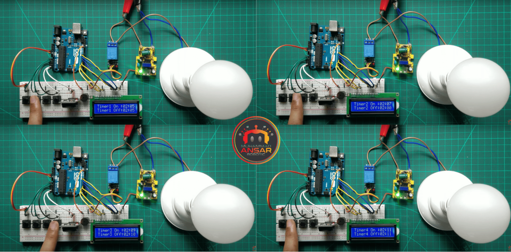
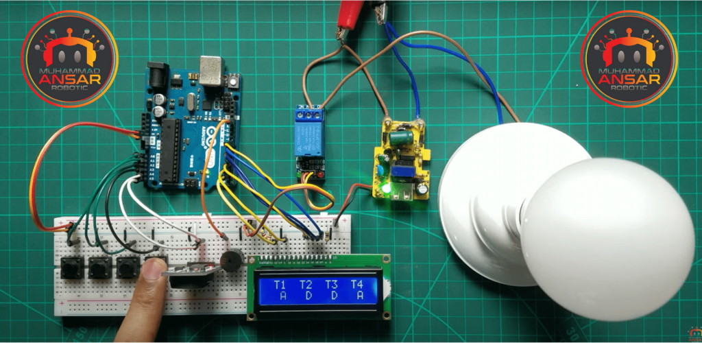
Hardware Testing
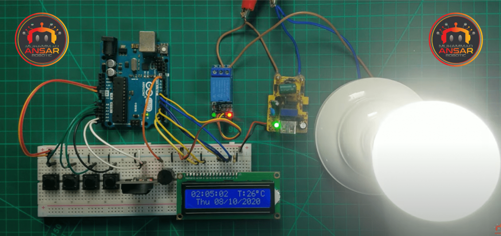
Conclusion
To sum up, this automatic home appliance management system that is based on a real-time clock is an excellent way to get started with home automation. You may add smart appliance scheduling to your living area by using easily accessible components and Arduino code. This project is a great place for DIY enthusiasts and aspiring home automation enthusiasts to start since the skills learned may be applied to more complicated automation settings.
One response to “Real Time Clock Based Automatic Home Appliances Control ”

Bro library error aa raha h
Library add ker Raha hu but Arduino me maximum library hone ke Karan nahi ho pa Raha hPlease bro please help me


One thought on “Real Time Clock Based Automatic Home Appliances Control ”
 VIKASH KUMAR says:
Bro library error aa raha h
Library add ker Raha hu but Arduino me maximum library hone ke Karan nahi ho pa Raha hPlease bro please help me
Leave a Reply