Real Time Clock With Alarm Using Arduino And RTC DS3231
Introduction
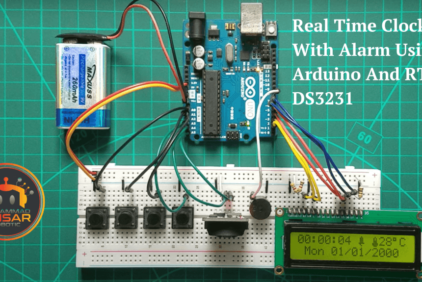
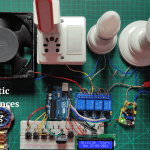
Making a Real Time Clock (RTC) with an alarm is a useful and instructive project for those who are new to Arduino. In order to maintain precise timekeeping and sound alerts when necessary, this project makes use of the DS3231 RTC module and the Arduino platform. The project’s adaptability is increased by the use of elements such as an LCD display, push button, and buzzer. Take a look at this detailed tutorial to get started with an interesting adventure with Arduino-based alarm and timekeeping devices.
Components Required
- Solderless Breadboard
- Arduino UNO
- 16×2 LCD Display
- Push Button
- RTC DS3231 Module
- 100R Resistor
- 4.7k Resistor
- 1k Resistor
- Buzzer
- Male to Male Jumper Wires
- Battery Clip
- 9V Battery
Proteus Simulation
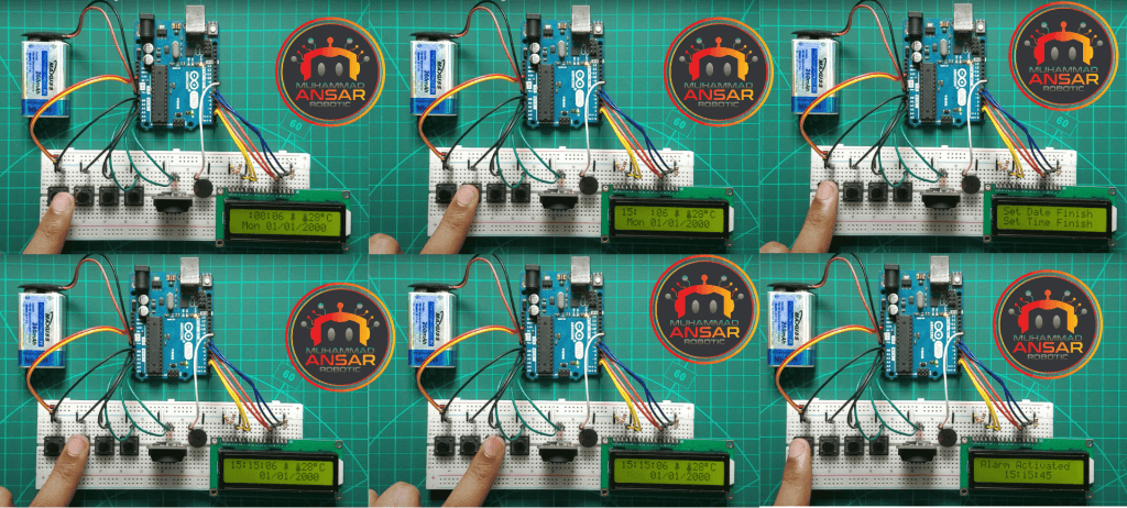
Open the Proteus 8 simulation file. An overview of the parts used, which include an Arduino Uno, an RTC-DS3231, four push buttons, a 16×2 LCD, and a buzzer, is given at the start of the presentation. The supplied Arduino code is used to create a hex file, which is then uploaded to the Arduino Uno via the Arduino IDE to start the simulation. The course emphasizes the critical processes of determining the address of the hex file, checking the code, and choosing the board (an Arduino Uno). The Arduino component is chosen in the Proteus simulation environment, and the previously acquired hex file address is pasted. Once the simulation is configured, the example runs the simulation and shows the start message display, temperature changes, time, and day, date, month, and year shown on the LCD. The lesson explores how to establish the real-time clock’s functionality. Pressing the “Set Time” button starts a series of steps that let users change the clock’s hours, minutes, seconds, day, date, month, and year. A thorough explanation of the procedure is given, with special attention to how the UP and DOWN buttons work to establish different settings. The “Set Alarm” button is then included, allowing users to modify the alarm’s date and time. Clear explanations of the “Activated” indicator and how to adjust the alarm length are given, along with how to activate and deactivate the alarm. The nuances of setting the alarm length in seconds and how it relates to the current time are explained.
Circuit Diagram
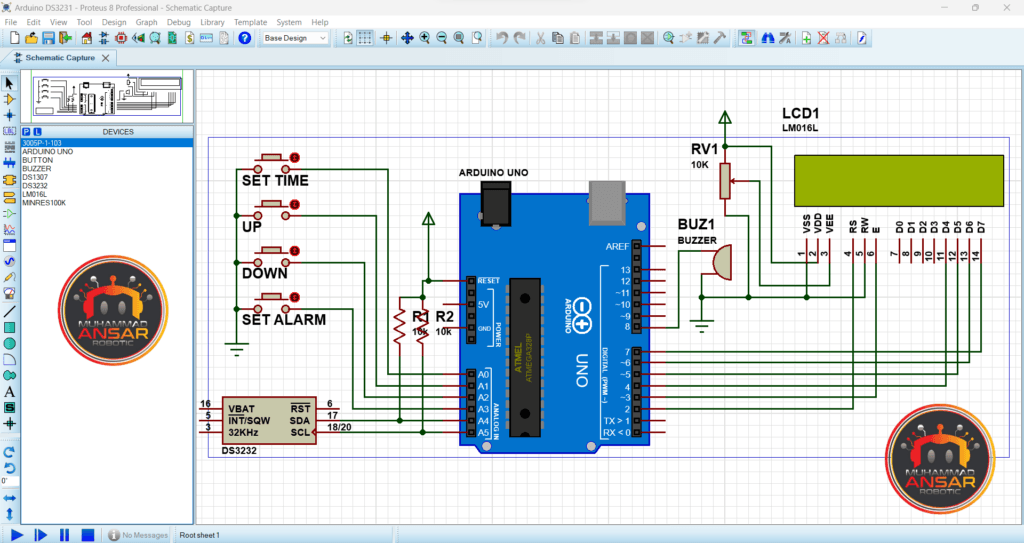
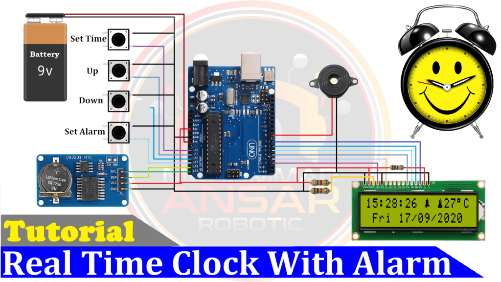
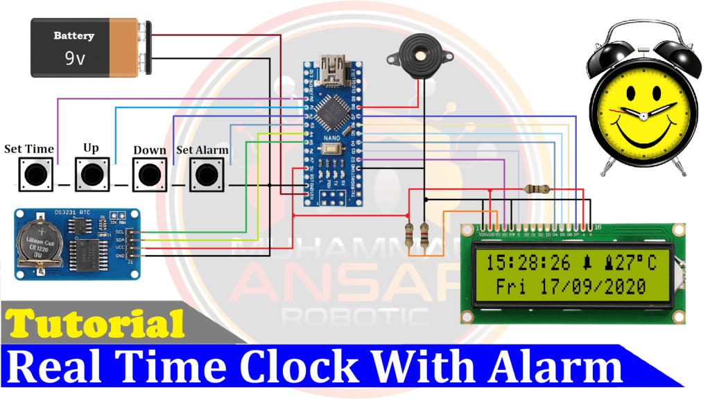
A 9V battery is used as the power supply in the circuit schematic for the Real Time Clock with an Alarm System Using Arduino and the RTC DS3231 module. The Arduino UNO is the main component, and it is supplemented by a 16×2 LCD display, a DS3231 RTC module, and four push buttons. The LCD’s contrast setting entails grounding the negative side, connecting 4.7k ohms to the positive side, and making extra connections for the backlight, which are anode to pin 15 and cathode to pin 16. A buzzer is introduced and connected to pin 8 of the Arduino UNO in order to add auditory feedback. Interestingly, the lighting circuit adds to the system’s total usefulness by connecting a 10-ohm resistor in series with the positive side. This circuit configuration makes sure that all of the parts work together seamlessly, enabling accurate timekeeping and alarm features. An alternate circuit schematic is supplied in case users decide to utilize an Arduino Nano rather than a UNO to carry out the project. The Nano is powered by a 9V battery in this setup, and analog pins A0 through A3 are where the push buttons are linked. It is easy to switch between the two Arduino versions since the connections for the RTC module, LCD, and buzzer are the same as they are for the UNO configuration.
Arduino IDE Code
#include <DS3231.h>//Memanggil RTC3231 Library
#include <Wire.h>  // i2C Conection Library
#include <LiquidCrystal.h> //Libraries
#include <EEPROM.h>

LiquidCrystal lcd(2, 3, 4, 5, 6, 7); //Arduino pins to lcd

#define bt_time   A0
#define bt_up     A1
#define bt_down   A2
#define bt_alarm  A3

#define buzzer 8

// Init DS3231
DS3231  rtc(SDA, SCL);

// Init a Time-data structure
Time  t; //pencacah string time()

int hh = 0, mm = 0, ss = 0, dd = 0, bb = 0, set_day;
int yy = 0;
String Day = "  ";

int AlarmHH  = 21, AlarmMM  = 22, AlarmSS  = 23, setMode = 0, setAlarm = 0, alarmMode=0;

int stop =0, mode=0, flag=0;

//Eeprom Store Variable
uint8_t HH;
uint8_t MM;

 byte bell_symbol[8] = {
        B00100,
        B01110,
        B01110,
        B01110,
        B01110,
        B11111,
        B01000,
        B00100};
byte thermometer_symbol[8] = {
        B00100,
        B01010,
        B01010,
        B01110,
        B01110,
        B11111,
        B11111,
        B01110};


void setup(){
// Setup Serial connection
  Serial.begin(9600);

  rtc.begin(); // memulai koneksi i2c dengan RTC

 pinMode(bt_time,  INPUT_PULLUP);
 pinMode(bt_up,    INPUT_PULLUP);
 pinMode(bt_down,  INPUT_PULLUP);
 pinMode(bt_alarm, INPUT_PULLUP);

 pinMode(buzzer, OUTPUT);

  lcd.createChar(1, thermometer_symbol);
  lcd.createChar(2, bell_symbol);

  lcd.begin(16, 2); // Configura lcd numero columnas y filas
  lcd.setCursor(0,0);  //Show "TIME" on the LCD

  lcd.setCursor (0,0);
  lcd.print(" Real Time Clock ");
  lcd.setCursor (0,1);
  lcd.print("   With Alarm ");
  delay (2000);
  lcd.clear();

stop=EEPROM.read(50);
if(stop==0){
}else{WriteEeprom ();}

EEPROM.write(50,0);

ReadEeprom();
//Set RTC Untuk Pertama kali
//rtc.setDOW(2);     // Set Day-of-Week to SUNDAY
//rtc.setTime (00, 9, 50);
//rtc.setDate(12, 11, 2017);
}

void loop(){
t = rtc.getTime();
Day = rtc.getDOWStr(1);

if (setMode == 0){
hh = t.hour,DEC;
mm = t.min,DEC;
ss = t.sec,DEC;
dd = t.date,DEC;
bb = t.mon,DEC;
yy = t.year,DEC;
}

  if(setAlarm==0){
  lcd.setCursor(0,0);
  lcd.print((hh/10)%10);
  lcd.print(hh % 10);
  lcd.print(":");
  lcd.print((mm/10)%10);
  lcd.print(mm % 10);
  lcd.print(":");
  lcd.print((ss/10)%10);
  lcd.print(ss % 10);
  lcd.print(" ");
  if(mode==1){lcd.write(2);}
  else{lcd.print(" ");}
  lcd.print(" ");
  lcd.write(1);
  lcd.print(rtc.getTemp(),0);
  lcd.write(223);
  lcd.print("C");
  lcd.print("  ");

  lcd.setCursor(1,1);
  lcd.print(Day);
  lcd.print(" ");
  lcd.print((dd/10)%10);
  lcd.print(dd % 10);
  lcd.print("/");
  lcd.print((bb/10)%10);
  lcd.print(bb % 10);
  lcd.print("/");
  lcd.print((yy/1000)%10);
  lcd.print((yy/100)%10);
  lcd.print((yy/10)%10);
  lcd.print(yy % 10);
  }


setupClock();
setTimer();
delay (100);
blinking();

//Alarm
if (alarmMode==1 && mode==1 && hh==AlarmHH && mm==AlarmMM && ss>=AlarmSS) {
digitalWrite(buzzer, HIGH);
delay (300);
digitalWrite(buzzer, LOW);
}else{digitalWrite(buzzer, LOW);}


delay (100);
}

void blinking (){
//BLINKING SCREEN
if (setAlarm <2 && setMode == 1){lcd.setCursor(0,0);  lcd.print("  ");}
if (setAlarm <2 && setMode == 2){lcd.setCursor(3,0);  lcd.print("  ");}
if (setAlarm <2 && setMode == 3){lcd.setCursor(6,0);  lcd.print("  ");}
if (setAlarm <2 && setMode == 4){lcd.setCursor(1,1);  lcd.print("   ");}
if (setAlarm <2 && setMode == 5){lcd.setCursor(5,1);  lcd.print("  ");}
if (setAlarm <2 && setMode == 6){lcd.setCursor(8,1);  lcd.print("  ");}
if (setAlarm <2 && setMode == 7){lcd.setCursor(11,1); lcd.print("    "); }
//Alarm
if (setMode == 0 && setAlarm == 1){lcd.setCursor(6,0); lcd.print("           "); }
if (setMode == 0 && setAlarm == 2){lcd.setCursor(4,1); lcd.print("  "); }
if (setMode == 0 && setAlarm == 3){lcd.setCursor(7,1); lcd.print("  "); }
if (setMode == 0 && setAlarm == 4){lcd.setCursor(10,1);lcd.print("  "); }
}

//Seting Jam ,Tanggal,Alarm/Timer
void setupClock (void) {

    if (setMode == 8){
    lcd.setCursor (0,0);
    lcd.print (F("Set Date Finish "));
    lcd.setCursor (0,1);
    lcd.print (F("Set Time Finish "));
    delay (1000);
    rtc.setTime (hh, mm, ss);
    rtc.setDate (dd, bb, yy);
    lcd.clear();
    setMode = 0;
    }

    if (setAlarm == 5){
    lcd.setCursor (0,0);
    lcd.print (F("Set Alarm Finish"));
    lcd.setCursor (0,1);
    lcd.print (F("-EEPROM Updated-"));
    WriteEeprom();
    delay (2000);
    lcd.clear();
    setAlarm=0;
    alarmMode=1;
    }

 if (setAlarm >0){ alarmMode=0;}

 if(digitalRead (bt_time) == 0 && flag==0) {flag=1;
 if(setAlarm>0){setAlarm=5;}
 else{setMode = setMode+1;}
 }

 if(digitalRead (bt_alarm) == 0 && flag==0){flag=1;
 if(setMode>0){setMode=8;}
  else{setAlarm = setAlarm+1;}
  lcd.clear();}

if(digitalRead (bt_time) == 1 && digitalRead (bt_alarm) == 1){flag=0;}

 if(digitalRead (bt_up) == 0){
            if (setAlarm<2 && setMode==1)hh=hh+1;
            if (setAlarm<2 && setMode==2)mm=mm+1;
            if (setAlarm<2 && setMode==3)ss=ss+1;
            if (setAlarm<2 && setMode==4)set_day=set_day+1;
            if (setAlarm<2 && setMode==5)dd=dd+1;
            if (setAlarm<2 && setMode==6)bb=bb+1;
            if (setAlarm<2 && setMode==7)yy=yy+1;
            //Alarm
            if (setMode==0 && setAlarm==1)mode=1;
            if (setMode==0 && setAlarm==2 && AlarmHH<23)AlarmHH=AlarmHH+1;
            if (setMode==0 && setAlarm==3 && AlarmMM<59)AlarmMM=AlarmMM+1;
            if (setMode==0 && setAlarm==4 && AlarmSS<59)AlarmSS=AlarmSS+1;

if(hh>23)hh=0;
if(mm>59)mm=0;
if(ss>59)ss=0;
if(set_day>7)set_day=0;
if(dd>31)dd=0;
if(bb>12)bb=0;
if(yy>2030)yy=2000;
rtc.setDOW(set_day);
 }

if(digitalRead (bt_down) == 0){
            if (setAlarm<2 && setMode==1)hh=hh-1;
            if (setAlarm<2 && setMode==2)mm=mm-1;
            if (setAlarm<2 && setMode==3)ss=ss-1;
            if (setAlarm<2 && setMode==4)set_day=set_day-1;
            if (setAlarm<2 && setMode==5)dd=dd-1;
            if (setAlarm<2 && setMode==6)bb=bb-1;
            if (setAlarm<2 && setMode==7)yy=yy-1;
            //Alarm
            if (setMode==0 && setAlarm==1 )mode=0;
            if (setMode==0 && setAlarm==2 && AlarmHH>0)AlarmHH=AlarmHH-1;
            if (setMode==0 && setAlarm==3 && AlarmMM>0)AlarmMM=AlarmMM-1;
            if (setMode==0 && setAlarm==4 && AlarmSS>0)AlarmSS=AlarmSS-1;
if(hh<0)hh=23;
if(mm<0)mm=59;
if(ss<0)ss=59;
if(set_day<0)set_day=7;
if(dd<0)dd=31;
if(bb<0)bb=12;
if(yy<0)yy=2030;
rtc.setDOW(set_day);
 }

}

void setTimer (){
  //Alarm
 if (setMode == 0 && setAlarm >0){
  lcd.setCursor (0,0);
  lcd.print("Alarm ");
 if(mode==0){lcd.print("Deactivate");}
        else{lcd.print("Activated ");}

  lcd.setCursor (4,1);
  lcd.print((AlarmHH/10)%10);
  lcd.print(AlarmHH % 10);
  lcd.print(":");
  lcd.print((AlarmMM/10)%10);
  lcd.print(AlarmMM % 10);
  lcd.print(":");
  lcd.print((AlarmSS/10)%10);
  lcd.print(AlarmSS % 10);
 }
}

void ReadEeprom () {
  AlarmHH=EEPROM.read(1);
  AlarmMM=EEPROM.read(2);
  AlarmSS=EEPROM.read(3);

  mode=EEPROM.read(4);
}

void WriteEeprom () {
  EEPROM.write(1,AlarmHH);
  EEPROM.write(2,AlarmMM);
  EEPROM.write(3,AlarmSS);

  EEPROM.write(4,mode);
}
Explanation
The RTC library is used for real-time clock functionality, the LCD library is used to interface with the 16×2 LCD display, and the EEPROM library is used to read and write data to the Arduino’s non-volatile memory. These libraries are called at the beginning of the code. The setup portion of the code initializes the pins for the buzzer, push buttons, and LCD. By doing this, the Arduino and the linked components are guaranteed to communicate and interact properly. The code defines a number of variables that are essential to the functioning of the application, including those that store the date, time, alarm settings, and mode indications. The real-time clock and alarm functions are mostly controlled by these factors. The function known as “void setup” sets up the RTC library, initializes the LCD display, configures push buttons and the buzzer pin, and sets the serial communication board rate. It also shows an introductory message on the LCD after a short 2000 millisecond delay. The time and date are continually received from the RTC module by the void loop function, which then breaks them down into their component parts (hour, minute, second, day, date, month, and year) and shows them on the LCD. Additionally, it makes calls to the alarm timer and real-time clock features. When users go into the setting mode to change the time or alarm settings, a certain function takes care of the blinking effect. By displaying the current parameter that has to be adjusted, this function facilitates user engagement. A comprehensive section for controlling the alarm functionality is included in the code. It efficiently illustrates the relationship between the real-time clock and the alarm system by checking conditions to decide when to trigger the buzzer depending on the established alarm time. The code includes routines to read and write data to the EEPROM memory of the Arduino, allowing alarm settings to be stored and retrieved even after a power cycle.
Hardware Testing
Conclusion
In conclusion, the Arduino Real Time Clock with Alarm System project, which makes use of the RTC DS3231 module, offers a thorough and approachable introduction to embedded systems. The methodically laid out stages, from Proteus simulation to code overview, make it easier to integrate the various parts for accurate timekeeping and alert features. In addition to producing a working gadget, this hands-on project encourages real-world learning about hardware interface and Arduino programming. The project is a great way for enthusiasts to learn about and play with the fascinating fields of electronics and programming since it places a strong emphasis on clarity and user interaction.
9 responses to “Real Time Clock With Alarm Using Arduino And RTC DS3231”

we are soo happy to get this code source and all , but we will contact you on the next step, thanks you sooo

code me erroor dikha raha hai

kia error dekha raha hy

Bhai library error h please give me library

Hey people!!!!!
Good mood and good luck to everyone!!!!!
Hey people!!!!!
Good mood and good luck to everyone!!!!!
thank you

are manual cars cheaper to maintain
CARFAX is an international provider of vehicle histories with the goal of making the used car market more transparent and our roads safer worldwide.
Have more questions? Browse articles by insurance type
Overview
What makes us special:
Will a manual transmission be cheaper to maintain than an automatic?
mental health app [url=www.mental-health23.com]mental health app[/url] .
9 thoughts on “Real Time Clock With Alarm Using Arduino And RTC DS3231”
we are soo happy to get this code source and all , but we will contact you on the next step, thanks you sooo
code me erroor dikha raha hai
Bhai library error h please give me library
Hey people!!!!!
Good mood and good luck to everyone!!!!!Hey people!!!!!
Good mood and good luck to everyone!!!!!are manual cars cheaper to maintain
CARFAX is an international provider of vehicle histories with the goal of making the used car market more transparent and our roads safer worldwide.
Have more questions? Browse articles by insurance type
Overview
What makes us special:
Will a manual transmission be cheaper to maintain than an automatic?mental health app [url=www.mental-health23.com]mental health app[/url] .


Leave a Reply