Introduction
The exact timing of bell schedules is crucial for upholding order and facilitating seamless transitions between classes and activities in educational institutions. However, human mistake can occur with older manual bell systems, which can cause disturbances to everyday routines. In order to simplify bell administration, this project presents an automated system that makes use of electronic components and Arduino technology. Schools may increase accuracy, dependability, and efficiency by automating the bell control process, which will eventually improve the quality of education for both teachers and students.
Components Required
- Solderless Breadboard
- Arduino UNO
- 16×2 LCD Display
- Push Button (x4)
- RTC DS3231 Module
- 10k Variable Resistor
- 100R Resistor
- Buzzer
- 1-Channel 5v Relay Module
- Male to Male Jumper Wires
- Male to Female Jumper Wires
- Electric School Bell 220V
- 5V 2Amp Power Adapter
Proteus Simulation
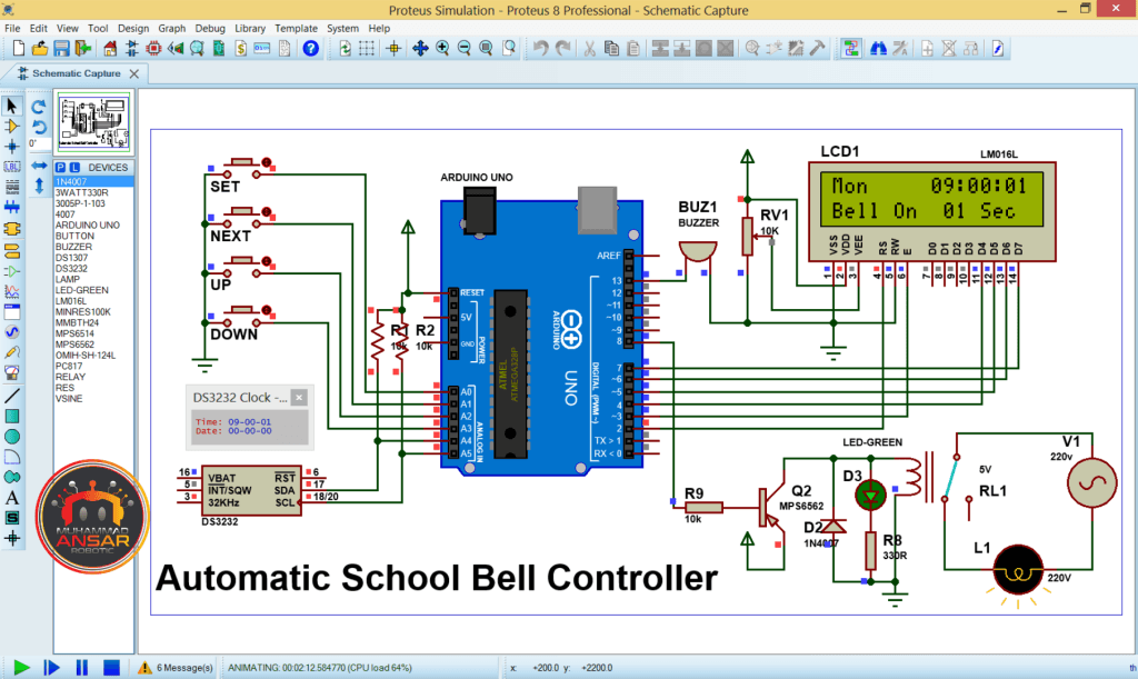
It is advised to use Proteus software to simulate the circuit before moving on with hardware development. Prior to actual assembly, this stage verifies that the design and functioning are accurate. Open the simulation file on proteus 8.12. Here, first of all, we have used Arduino UNO. Then, here, we have used RTC module DS3231. We have used a relay module. We have used it for switching of 220V. In simulation, we have used a 220V bulb instead of bell. Then, a 16×2 LCD is used as display. Then, a buzzer is used. Generate hex file to run the simulation by opening and compiling the Arduino code. Copy the address and include it in the simulation. When we run the file, first message is displayed on the LCD for 2000 milliseconds delay. Then, we have displayed time and day with it on the first line. And on the second line, we have updated the status of the next bell. If we have power in the RTC module first time, it will start from 00-00-00. From buttons, we have to set the date and time. For that, you have to press the button of SET. Set the day, as today is Wednesday. Press the UP and DOWN buttons, and set the day as Wednesday. Similarly, by pushing the SET button again, it will be in time setting. Set the clock according to 24 hours. When hours are set, push the next button, it will be now setting the minutes. Now, we will again press the SET button to set the bell timing. A period for which the bell will be on. We have kept it 2 seconds. Press the SET button to set the weekend. Weekend is starting from Friday or Saturday. After this, press the SET button. We have set it as week days. For this, it will be the same for whole week. If we have to set different time, we can do this by selecting day and set its time individually. Then, again press the SET button. Here, we are in set bell condition. We can set 30 bell timings for one day. According to 24 hours, we can set the times for all bells. In the same way, we will press NEXT. The time for first bell will be stored. And similarly it will store the time for next bells.
Circuit Diagram
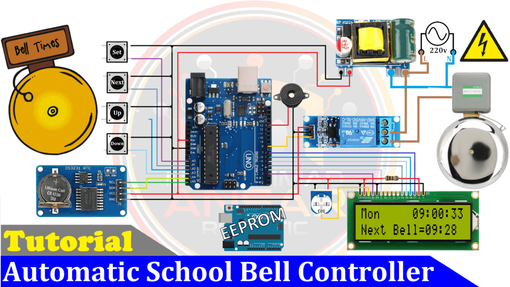
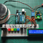
In the circuit diagram provided, a 220V power source serves as the primary input. This power is then converted to a stable 5V and 2A output for the subsequent circuitry. The core of the system is an Arduino UNO, which interfaces with four push buttons for user input. Additionally, an RTC module (DS3231) is utilized for accurate timekeeping, while a 16×2 LCD display provides visual feedback. A 10k ohm potentiometer is employed for contrast adjustment on the LCD, with backlight pins (15 and 16) powered accordingly. A 5V relay module enables the switching of the 220V electric bell, with one terminal connected to the power source and the other to the common and normally open terminals of the relay, respectively. Furthermore, a buzzer is incorporated into the circuit for auditory notifications.
Arduino IDE Code
<code>
#include <LiquidCrystal.h> //Libraries
#include <EEPROM.h>
#include <Wire.h>  // i2C Conection Library

LiquidCrystal lcd(2, 3, 4, 5, 6, 7);

#define bt_set  A0
#define bt_next A1
#define bt_up   A2
#define bt_down A3

#define relay  8
#define buzzer 13

//RTC DS3231
#define DS3231_I2C_ADDRESS 0x68 //address of DS3231 module

int hh=0, mm=0, ss=0, set_day=0, set_time=0, run_time=0, set_week=0;
int StartHH=0, StartMM=0, Alarm=0, weekend=0;
int set=0, setMode=0, max=30;
int flag0=2, flag1=0, flag2=0, flag3=1;
int flash=0;

word MilliSecond = 0;
bool timerStart = false;

String show_day[8] = {"","Mon","Tue","Wed","Thr","Fri","Sat","Sun"};

void setup(){
Wire.begin(); //start I2C communication


pinMode(bt_set,  INPUT_PULLUP);
pinMode(bt_next, INPUT_PULLUP);
pinMode(bt_up,   INPUT_PULLUP);
pinMode(bt_down, INPUT_PULLUP);

pinMode(relay, OUTPUT);
pinMode(buzzer, OUTPUT);

digitalWrite(relay, 1);

lcd.begin(16, 2); // Configura lcd numero columnas y filas
lcd.setCursor(0,0);  //Show "TIME" on the LCD
lcd.print("   Welcome To   ");
lcd.setCursor(0,1);
lcd.print("Auto School Bell");

if(EEPROM.read(0)==0){
}else{
for(int x=1; x<max; x++){
WriteEeprom(1,x); delay(2);
WriteEeprom(2,x); delay(2);
WriteEeprom(3,x); delay(2);
WriteEeprom(4,x); delay(2);
WriteEeprom(5,x); delay(2);
WriteEeprom(6,x); delay(2);
WriteEeprom(7,x); delay(2);
 }
EEPROM.write(0,0);
EEPROM.write(10,0);
EEPROM.write(11,0);
}

set_time = EEPROM.read(10);
weekend  = EEPROM.read(11);

delay(2000);
lcd.clear();

noInterrupts();         // disable all interrupts
TCCR1A = 0;             // set entire TCCR1A register to 0  //set timer1 interrupt at 1kHz  // 1 ms
TCCR1B = 0;             // same for TCCR1B
TCNT1  = 0;             // set timer count for 1khz increments
OCR1A = 1999;           // = (16*10^6) / (1000*8) - 1
//had to use 16 bit timer1 for this bc 1999>255, but could switch to timers 0 or 2 with larger prescaler
// turn on CTC mode
TCCR1B |= (1 << WGM12); // Set CS11 bit for 8 prescaler
TCCR1B |= (1 << CS11);  // enable timer compare interrupt
TIMSK1 |= (1 << OCIE1A);
interrupts();           // enable
}

void loop() {
GetRtc();

if(ss==0){
if(flag0==0 || flag0==2){flag0=0;
Alarm = EEPROM.read(set_day);
for(int x=1; x<Alarm+1; x++){
ReadEeprom(set_day,x);
if(StartHH==hh && StartMM==mm){ run_time = set_time;
digitalWrite(relay, 0);
timerStart = true;
if(Alarm==x) flag3=1;
       else {flag3=0; ReadEeprom(set_day,x+1);}
   x=100;
   }
  }
 }
}else{flag0=0;}

if(digitalRead(bt_set)==0){ digitalWrite(buzzer, 1);
if(flag1==0){flag1=1;
setMode = setMode+1;
if(setMode==6){
if(set_week==0)Alarm=1;
         else{
Alarm = EEPROM.read(set_week);
ReadEeprom(set_week,Alarm);
}
}
if(setMode>6)setMode=0,set_week=0;
lcd.clear();
 }
}else{flag1=0;}


if(digitalRead(bt_next)==0){ digitalWrite(buzzer, 1);
if(flag2==0){flag2=1;
if(setMode==2){set=!set;}
if(setMode==6){set=set+1;
if(set>2){set=0;
if(set_week==0){
for(int x=1; x<weekend+1; x++){
WriteEeprom(x,Alarm);
 }
}else{
WriteEeprom(set_week,Alarm);
}
lcd.clear();
lcd.setCursor(0,0);
lcd.print("   Ok Stored");
delay(500);
lcd.clear();
if(Alarm<max)Alarm=Alarm+1;
   }
  }
 }
}else{flag2=0;}

if(digitalRead(bt_up)==0){digitalWrite(buzzer, 1);
if(setMode==1){set_day = set_day+1;
if(set_day>7)set_day=1;
SetRtc(ss, mm, hh,set_day);
}

if(setMode==2){
if(set==0)hh=hh+1;
     else mm=mm+1;
if(hh>23)hh=0;
if(mm>59)mm=0;
SetRtc(ss, mm, hh,set_day);
}

if(setMode==3){
set_time = set_time+1;
if(set_time>99)set_time=1;
EEPROM.write(10,set_time);
}

if(setMode==4){
weekend = weekend+1;
if(weekend>7)weekend=1;
EEPROM.write(11,weekend);
}

if(setMode==5){
set_week = set_week+1;
if(set_week>7)set_week=0;
}

if(setMode==6){
if(set==0)Alarm=Alarm+1;
if(set==1)StartHH=StartHH+1;
if(set==2)StartMM=StartMM+1;

if(Alarm>max)Alarm=1;
if(set==0 && set_week>0)ReadEeprom(set_week,Alarm);

if(StartHH>23)StartHH=0;
if(StartMM>59)StartMM=0;
}

delay(50);
}

if(digitalRead(bt_down)==0){ digitalWrite(buzzer, 1);
if(setMode==1){set_day = set_day-1;
if(set_day<1)set_day=7;
SetRtc(ss, mm, hh,set_day);
}

if(setMode==2){
if(set==0)hh=hh-1;
     else mm=mm-1;
if(hh<0)hh=23;
if(mm<0)mm=59;
SetRtc(ss, mm, hh,set_day);
}

if(setMode==3){
set_time = set_time-1;
if(set_time<1)set_time=99;
EEPROM.write(10,set_time);
}

if(setMode==4){
weekend = weekend-1;
if(weekend<1)weekend=7;
EEPROM.write(11,weekend);
}

if(setMode==5){
set_week = set_week-1;
if(set_week<0)set_week=7;
}

if(setMode==6){
if(set==0)Alarm=Alarm-1;
if(set==1)StartHH=StartHH-1;
if(set==2)StartMM=StartMM-1;

if(Alarm<1)Alarm=max;
if(set==0 && set_week>0)ReadEeprom(set_week,Alarm);

if(StartHH<0)StartHH=23;
if(StartMM<0)StartMM=59;
}

delay(50);
}


if(setMode>0)flash=!flash;
Display();
delay(150);
digitalWrite(buzzer, LOW);
}


void Display(){
if(setMode==0){
lcd.setCursor(0,0);
lcd.print(show_day[set_day]);
lcd.print("    ");
lcd.setCursor(8,0);
lcd.print((hh/10)%10);
lcd.print(hh % 10);
lcd.print(":");
lcd.print((mm/10)%10);
lcd.print(mm % 10);
lcd.print(":");
lcd.print((ss/10)%10);
lcd.print(ss % 10);

lcd.setCursor(0,1);
if(timerStart == true){
lcd.print("Bell On  ");
lcd.print((run_time/10)%10);
lcd.print(run_time % 10);
lcd.print(" Sec  ");
}else{
lcd.print("Next Bell=");
if(flag3==0){
lcd.print((StartHH/10)%10);
lcd.print(StartHH % 10);
lcd.print(":");
lcd.print((StartMM/10)%10);
lcd.print(StartMM % 10);
}else{lcd.print("##:##");}
 }
}

if(setMode==1){
lcd.setCursor(0,0);
lcd.print("SET Day");
lcd.setCursor(1,1);
if(flash)lcd.print(show_day[set_day]);
    else lcd.print("   ");
}

if(setMode==2){
lcd.setCursor(0,0);
lcd.print("SET Clock");
lcd.setCursor(1,1);
if(flash){
lcd.print((hh/10)%10);
lcd.print(hh % 10);
lcd.print(":");
lcd.print((mm/10)%10);
lcd.print(mm % 10);
}
else{
if(set==0)lcd.setCursor(1,1);
if(set==1)lcd.setCursor(4,1);
lcd.print("  ");
 }
}


if(setMode==3){
lcd.setCursor(0,0);
lcd.print("SET Bell Time");
lcd.setCursor(1,1);
if(flash){
lcd.print((set_time/10)%10);
lcd.print(set_time % 10);
}else lcd.print("  ");

lcd.print(" Sec");
}

if(setMode==4){
lcd.setCursor(0,0);
lcd.print("SET Weekend");
lcd.setCursor(1,1);
if(flash){
lcd.print(show_day[weekend]);
}else lcd.print("   ");
}


if(setMode==5){
lcd.setCursor(0,0);
lcd.print("SET Bell for");
lcd.setCursor(1,1);
if(flash){
if(set_week==0)lcd.print("Week Days");
          else lcd.print(show_day[set_week]);
}else     lcd.print("         ");
}

if(setMode==6){
lcd.setCursor(0,0);
lcd.print("SET Bell");
if(flash){
lcd.setCursor(1,1);
lcd.print((Alarm/10)%10);
lcd.print(Alarm % 10);
lcd.print("/");
lcd.print((max/10)%10);
lcd.print(max % 10);

lcd.setCursor(8,1);
lcd.print("T=");
lcd.print((StartHH/10)%10);
lcd.print(StartHH % 10);
lcd.print(":");
lcd.print((StartMM/10)%10);
lcd.print(StartMM % 10);
}else{
     if(set==0)lcd.setCursor(1,1);
else if(set==1)lcd.setCursor(10,1);
else if(set==2)lcd.setCursor(13,1);
lcd.print("  ");
  }
 }
}

//Set RTC
void SetRtc(byte second, byte minute, byte hour, byte dayOfWeek) {
  Wire.beginTransmission(DS3231_I2C_ADDRESS);
  Wire.write(0); //set 0 to first register
  Wire.write(decToBcd(second)); //set second
  Wire.write(decToBcd(minute)); //set minutes
  Wire.write(decToBcd(hour)); //set hours
  Wire.write(decToBcd(dayOfWeek)); //set day of week (1=su, 2=mo, 3=tu)
  Wire.endTransmission();
}

//read RTC
void GetRtc() {
  Wire.beginTransmission(DS3231_I2C_ADDRESS);
  Wire.write(0); //write "0"
  Wire.endTransmission();
  Wire.requestFrom(DS3231_I2C_ADDRESS, 7);  //request - 7 bytes from RTC
  ss = bcdToDec(Wire.read() & 0x7f);
  mm = bcdToDec(Wire.read());
  hh = bcdToDec(Wire.read() & 0x3f);
  set_day = bcdToDec(Wire.read());
}

//conversion Dec to BCD
byte decToBcd(byte val) {
  return((val / 10 * 16) + (val % 10));
}

//conversion BCD to Dec
byte bcdToDec(byte val) {
  return((val / 16 * 10) + (val % 16));
}


void ReadEeprom(int _day, int _alarm) {
int eeprom = (_day*100)+_alarm*3;
StartHH=EEPROM.read(eeprom);
StartMM=EEPROM.read(eeprom+1);
}

void WriteEeprom(int _day, int _alarm) {
int eeprom = (_day*100)+_alarm*3;
EEPROM.write(eeprom,StartHH);
EEPROM.write(eeprom+1,StartMM);
EEPROM.write(_day,Alarm);
}

ISR(TIMER1_COMPA_vect){
if(timerStart == true){MilliSecond++;
    if(MilliSecond >= 1000){MilliSecond = 0;
    run_time = run_time-1;
    if(run_time<=0){timerStart = false; digitalWrite(relay, 1);}
    }
  }
}
</code>
Explanation
- Libraries and Definitions: The necessary libraries such as LiquidCrystal, EEPROM, and Wire are included, along with defining pin assignments for buttons, relay, and buzzer.
- Global Variables: Variables are declared to store time values, set mode, flags, and other parameters used throughout the program.
- Setup() Function: Initializes the Arduino, LCD display, and sets up the RTC. It also configures the timer interrupt for precise timing.
- Loop() Function: The main execution loop of the program. It continuously checks for button presses, updates time values, and controls the bell activation based on the set schedule.
- Display() Function: Displays relevant information on the LCD based on the set mode and current parameters such as day, time, and bell settings.
- SetRtc() and GetRtc() Functions: Handle setting and reading time values from the RTC module.
- EEPROM Read and Write Functions: Manage reading and writing bell schedule data to EEPROM memory.
- Timer Interrupt Service Routine (ISR): Handles the timing of the bell activation, ensuring precise timing control.
Hardware Working
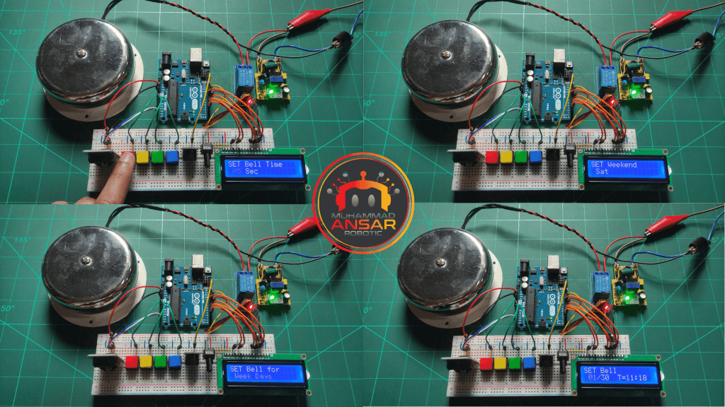
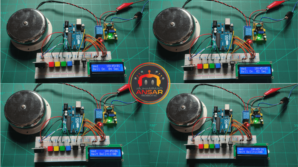
After building the circuit on the breadboard and uploading the code to the Arduino, it is critical to do hardware tests. Ensure that all components are working properly and that the school bell rings at the designated times.

Conclusion
Automating the school bell system reduces management while simultaneously improving precision and dependability. This research highlights how current technology may simplify regular chores in educational settings. Experiment with the code and circuit to tailor the system to individual needs and increase its capabilities further.
One response to “Automatic School Bell Controller”

Your circuit is very helpful as I tried and it worked!!!


Leave a Reply